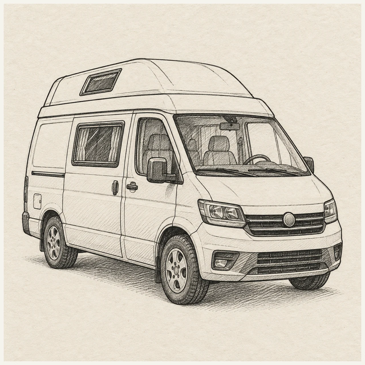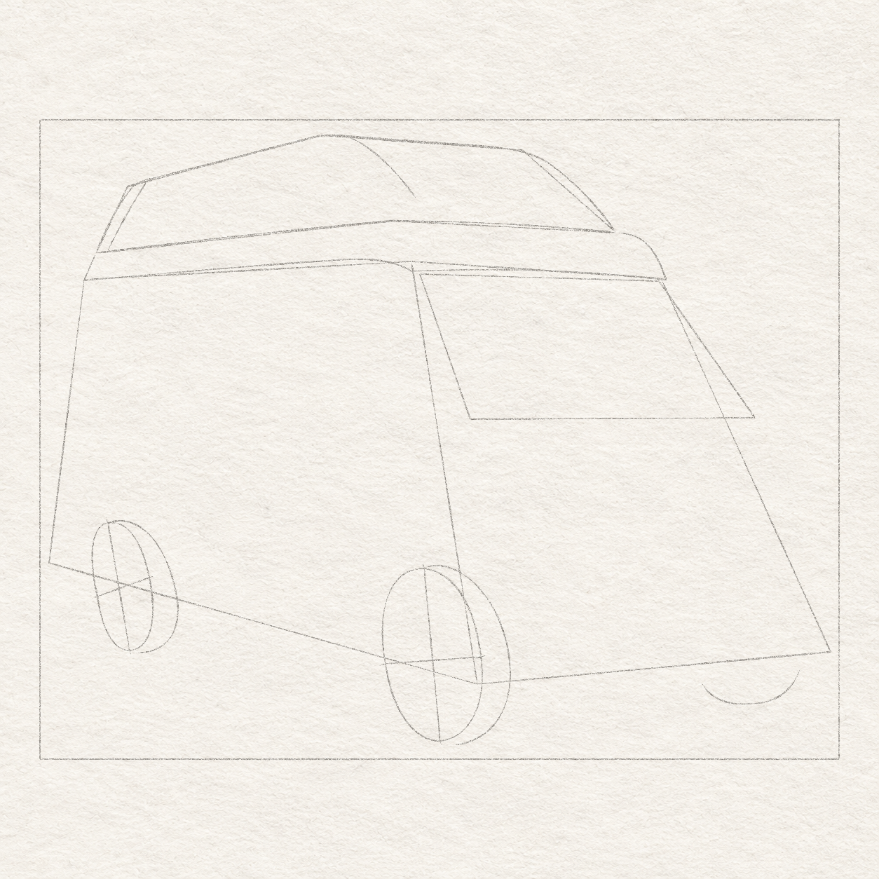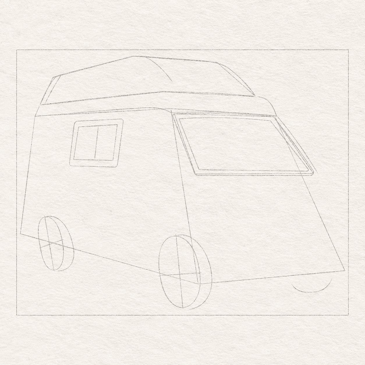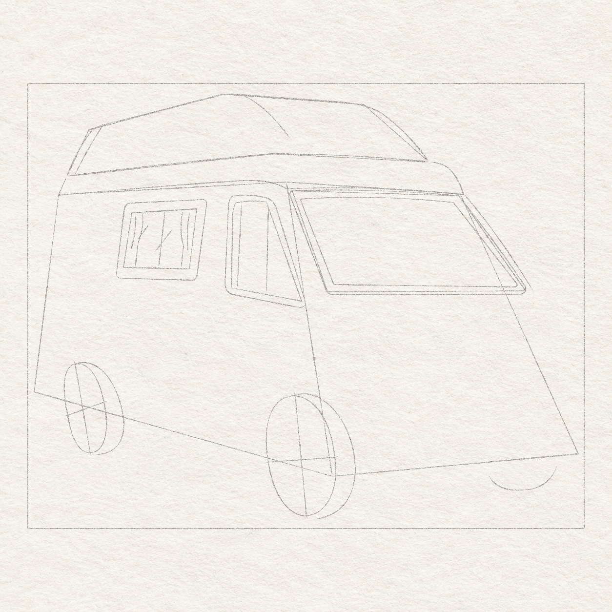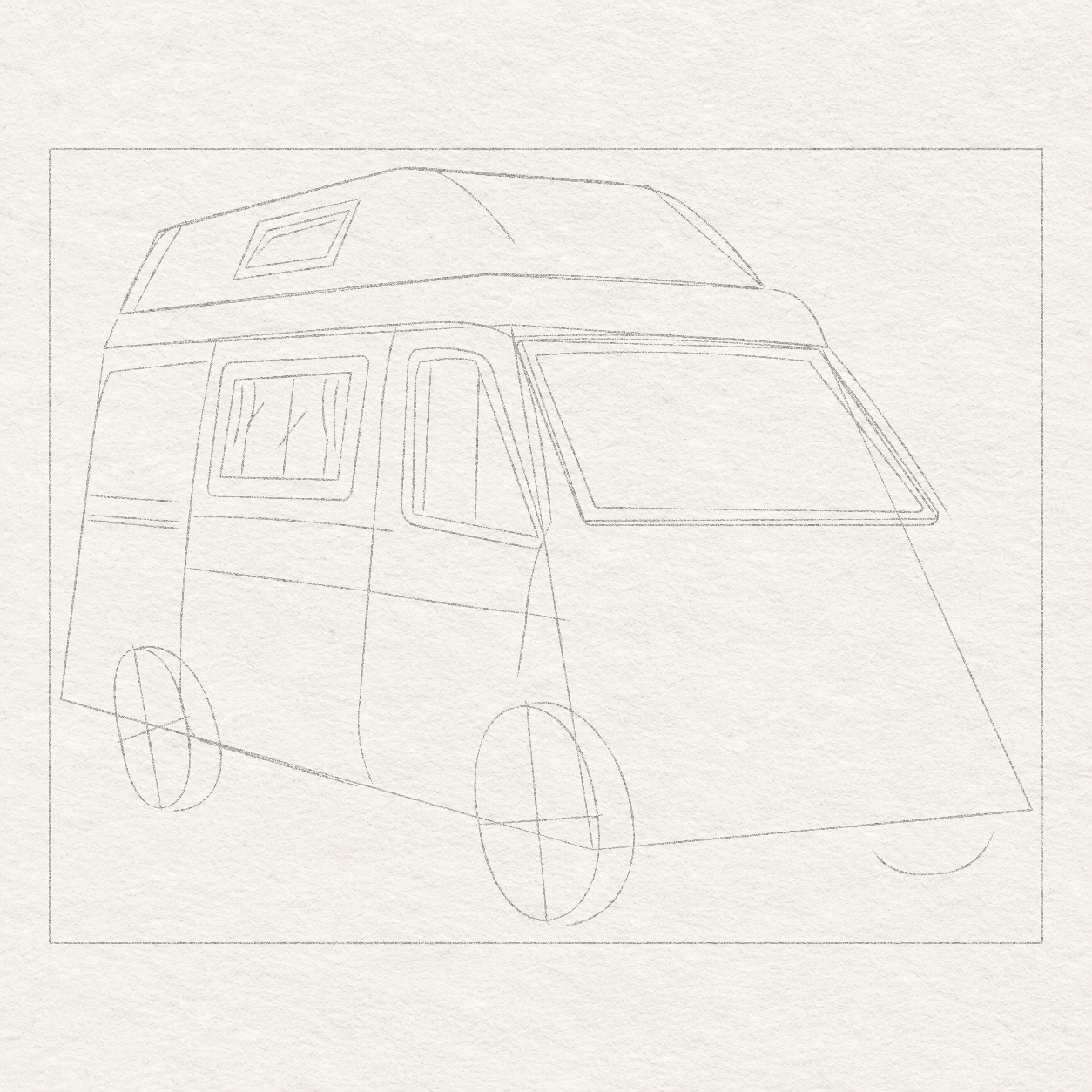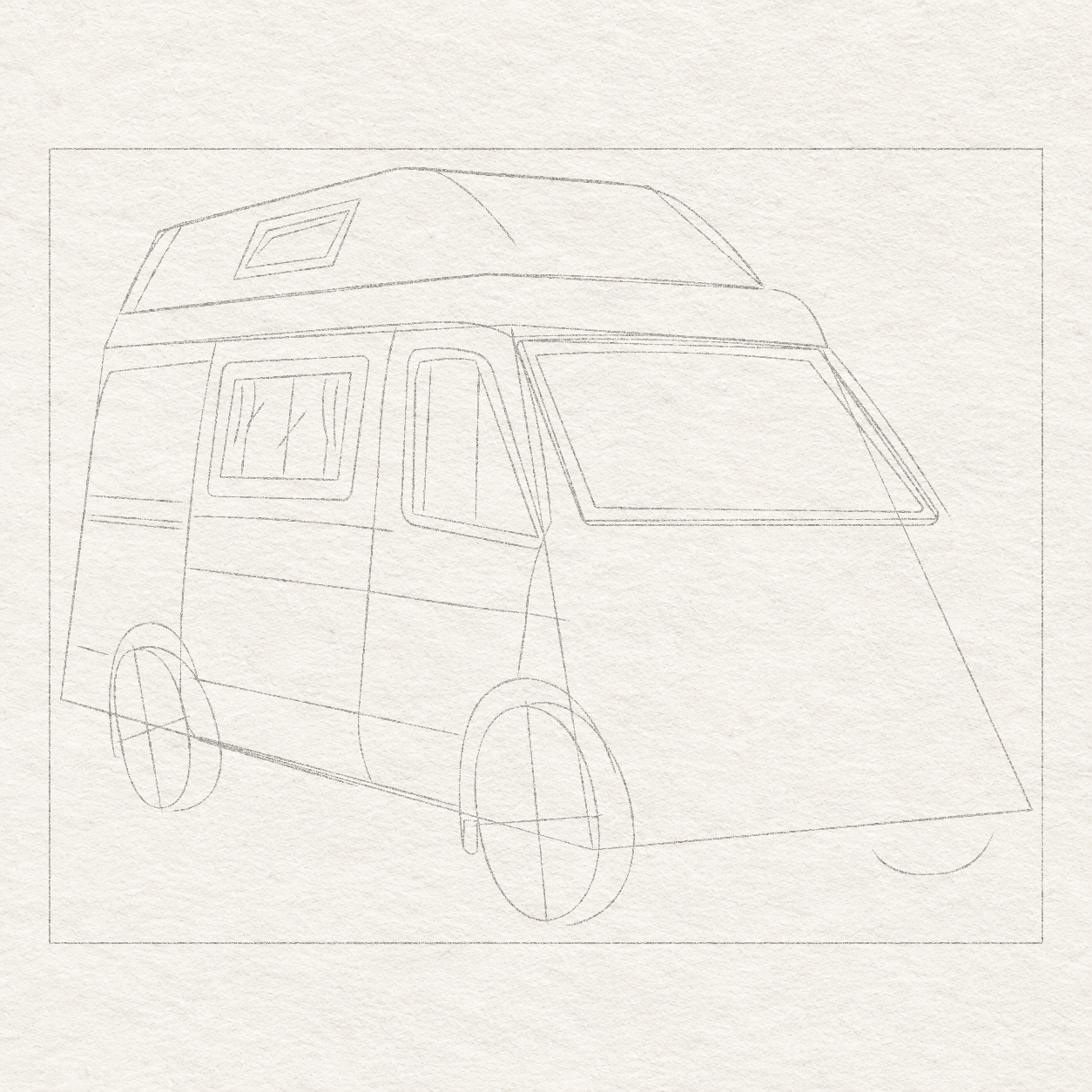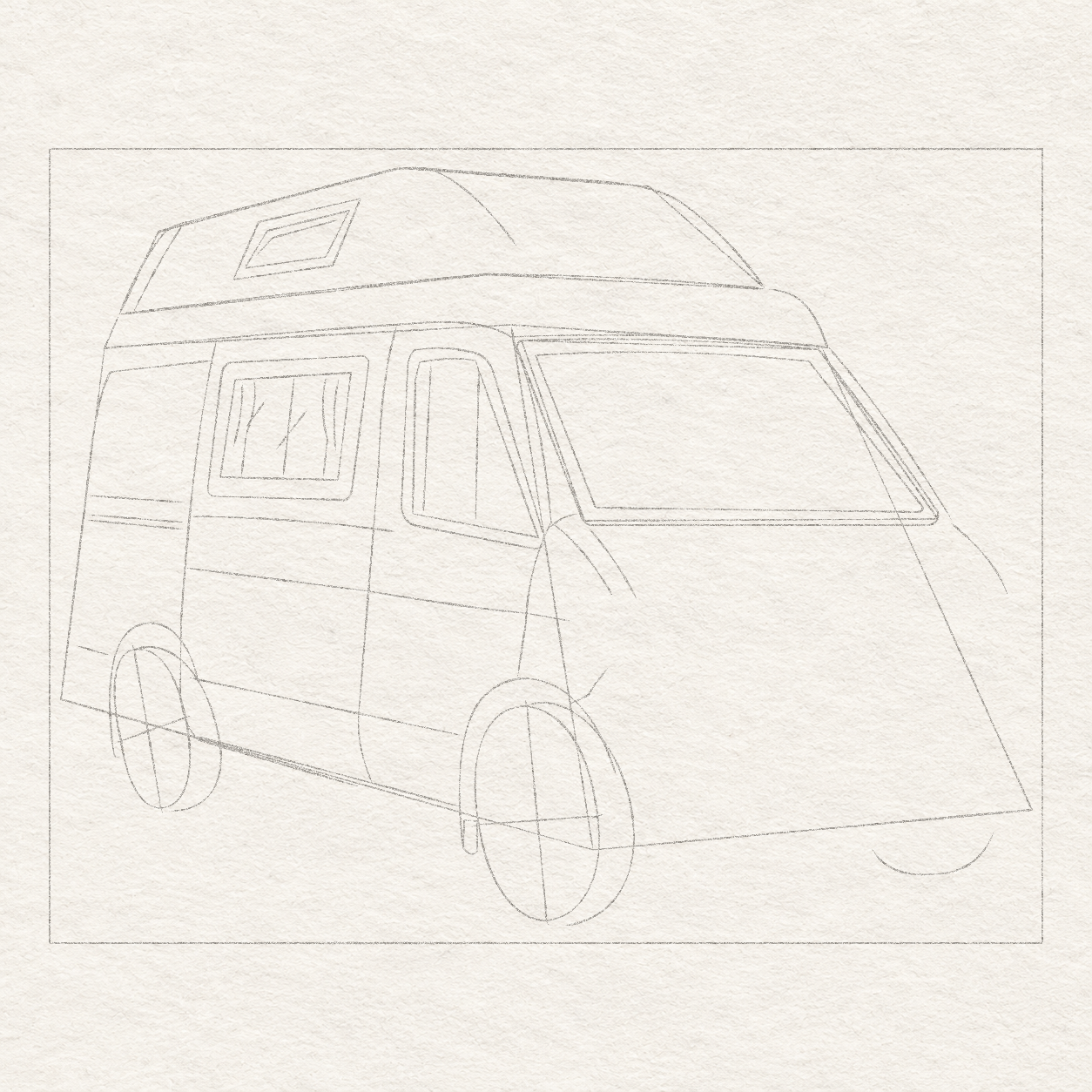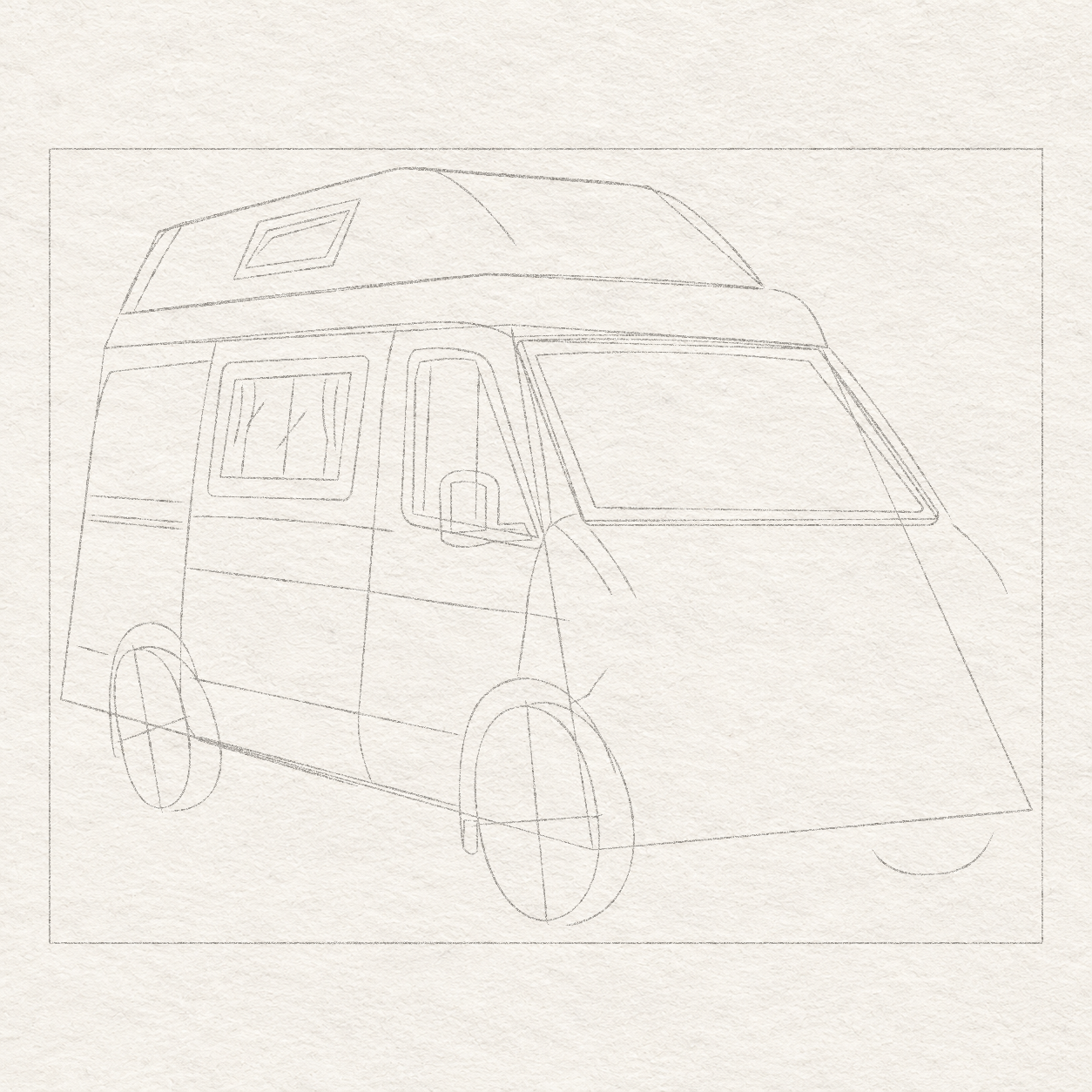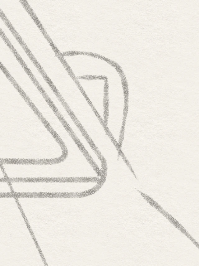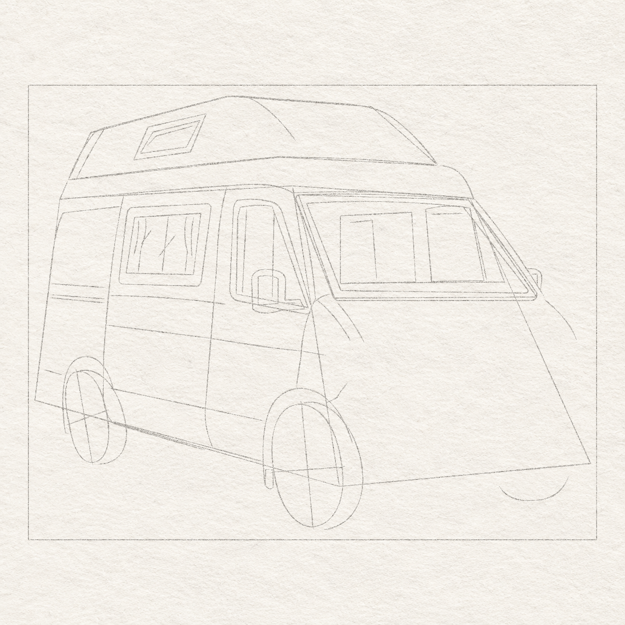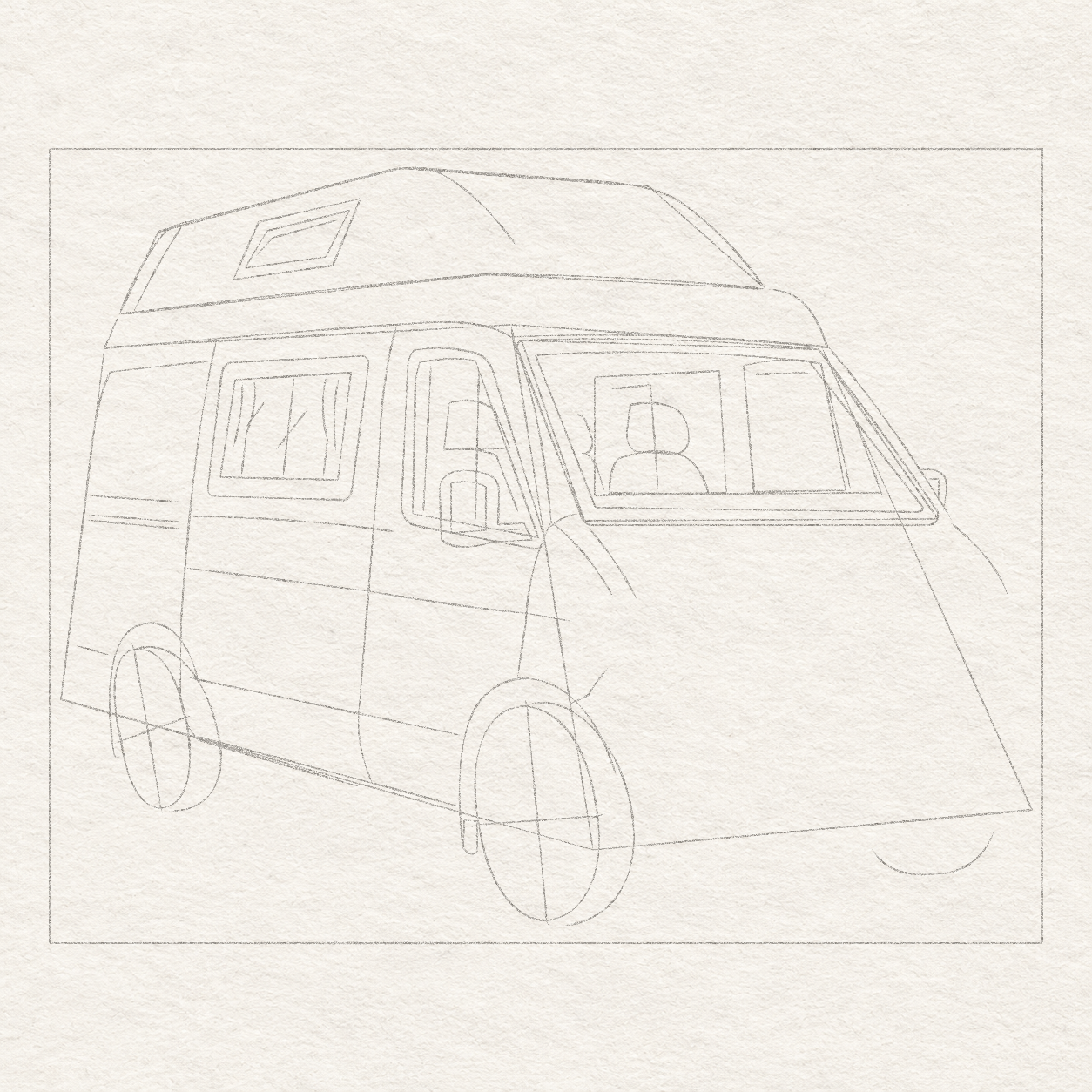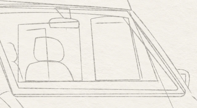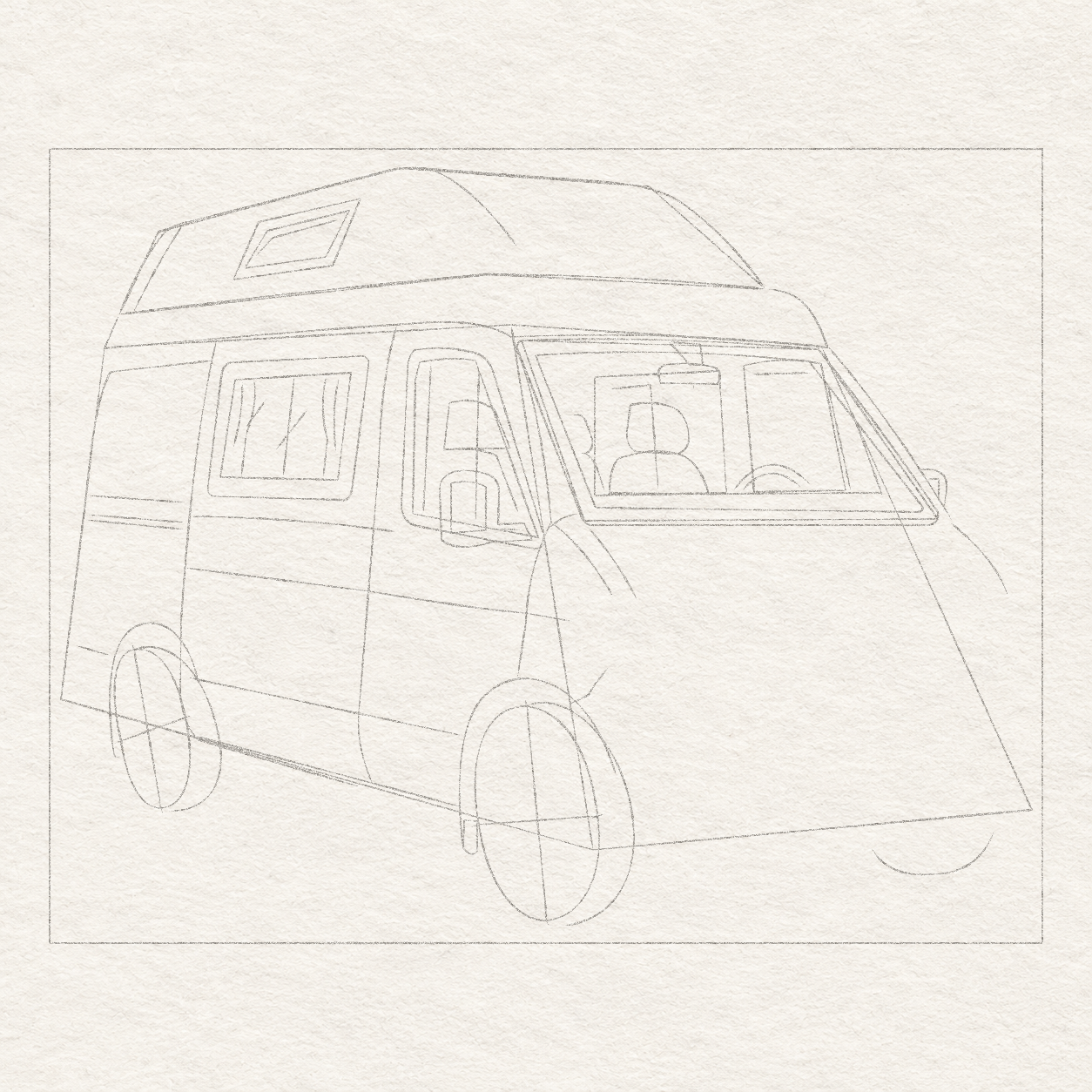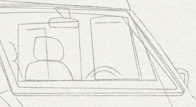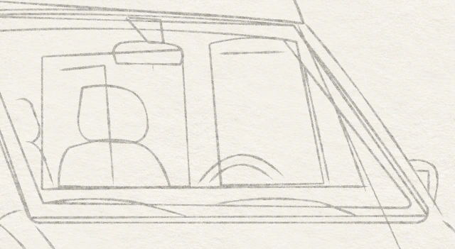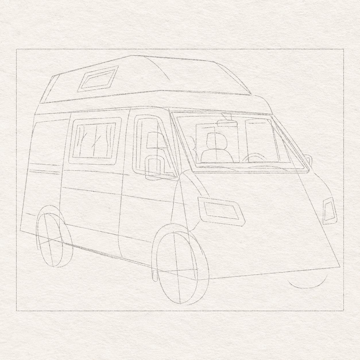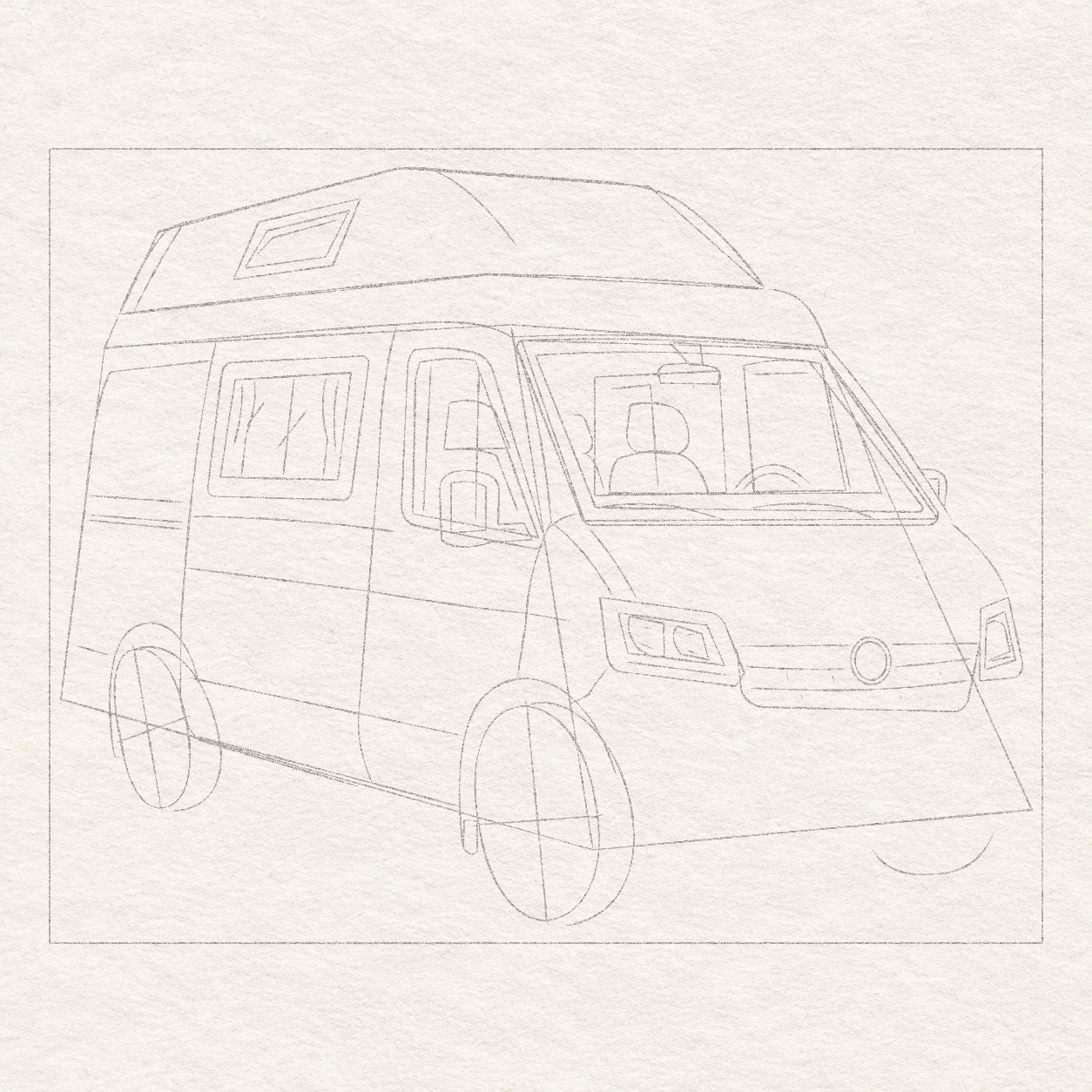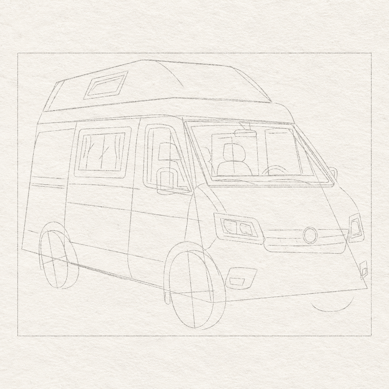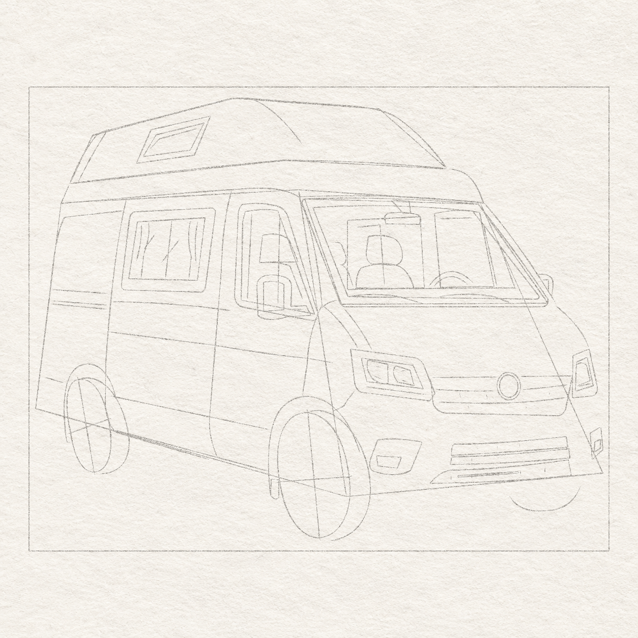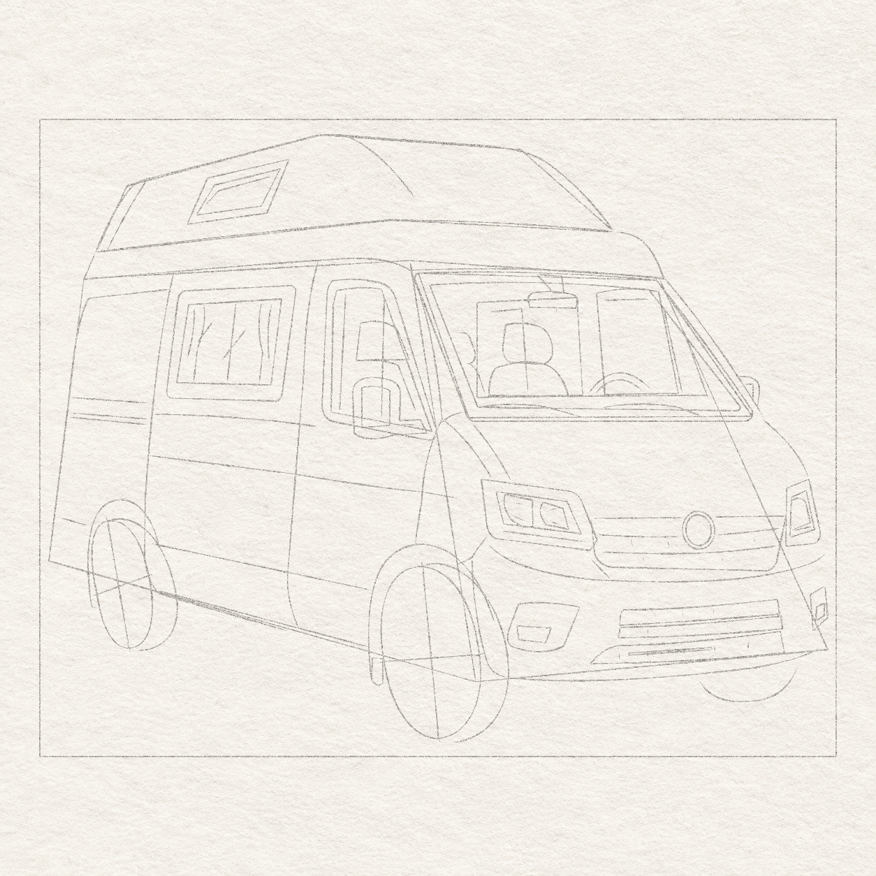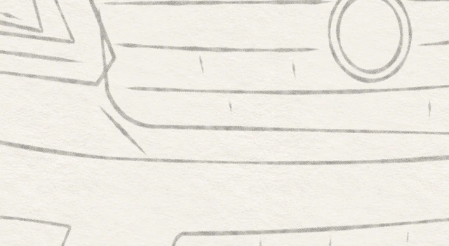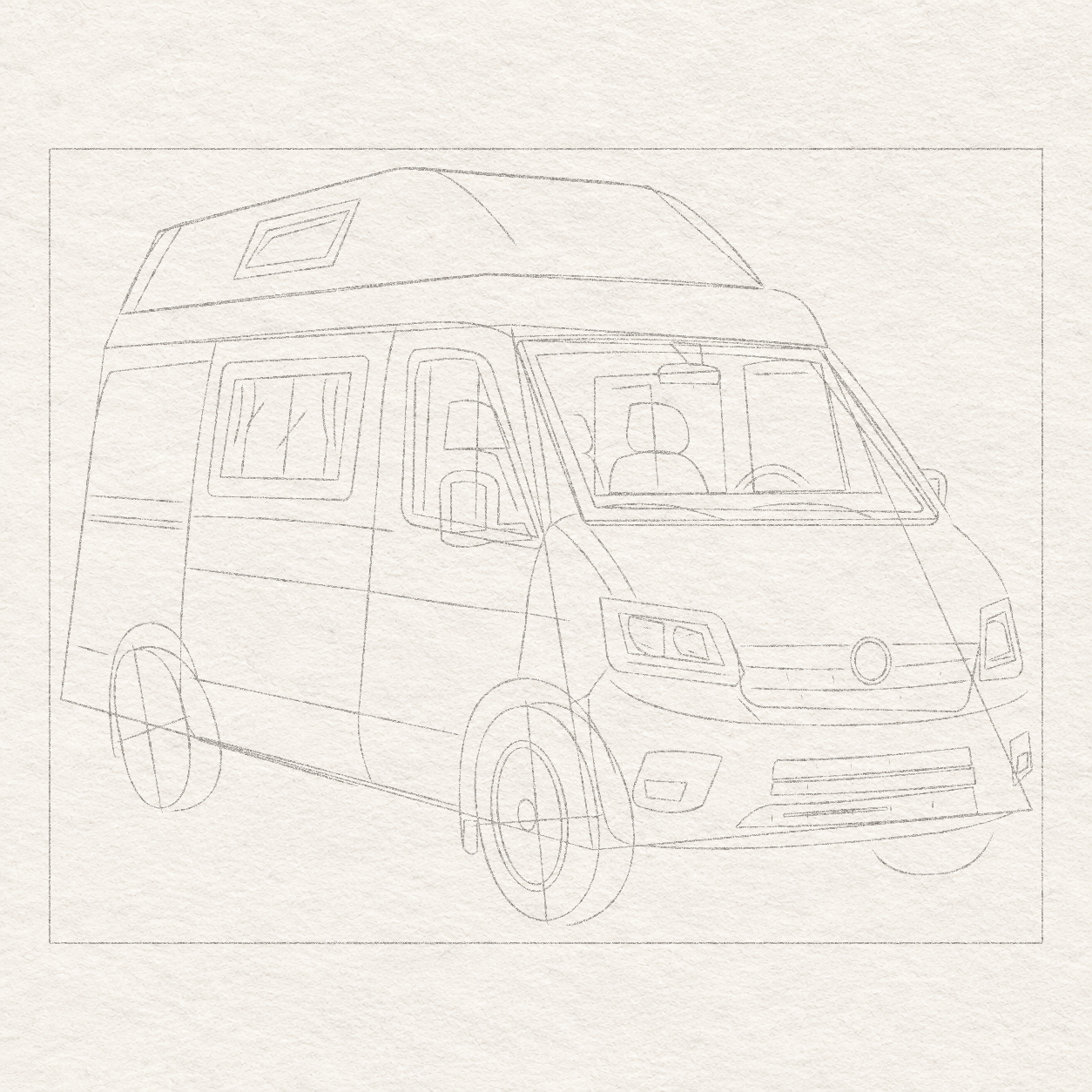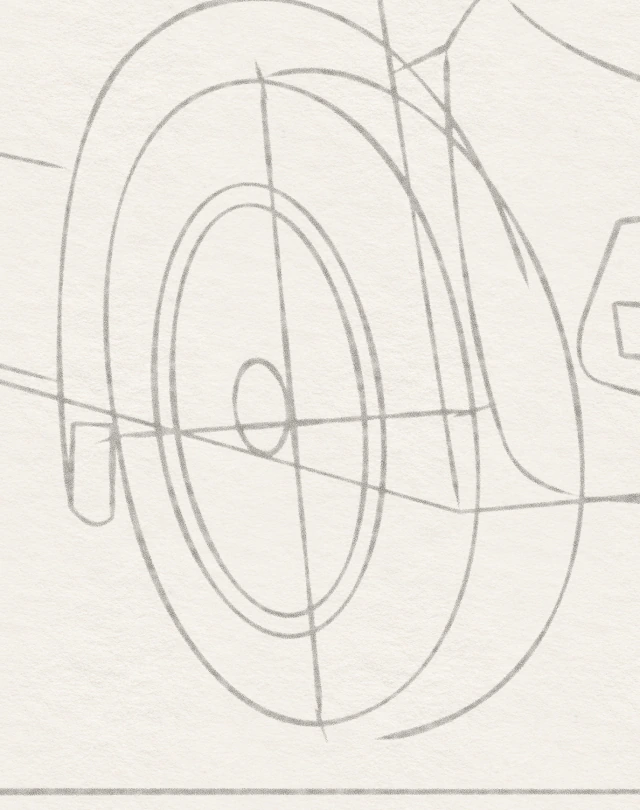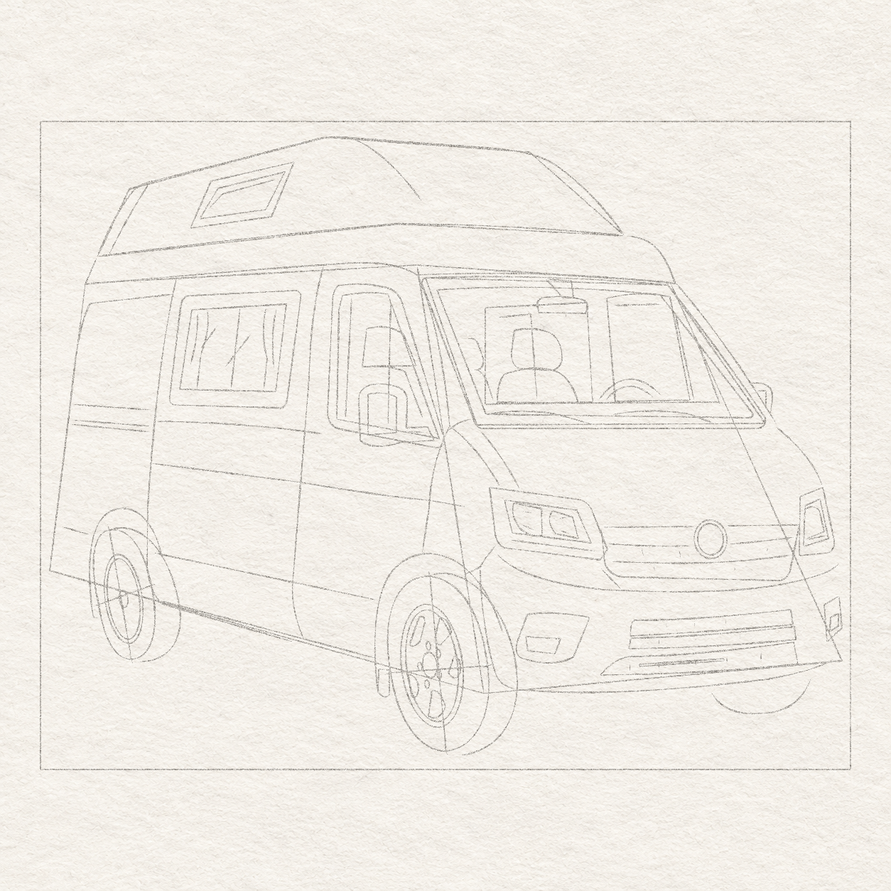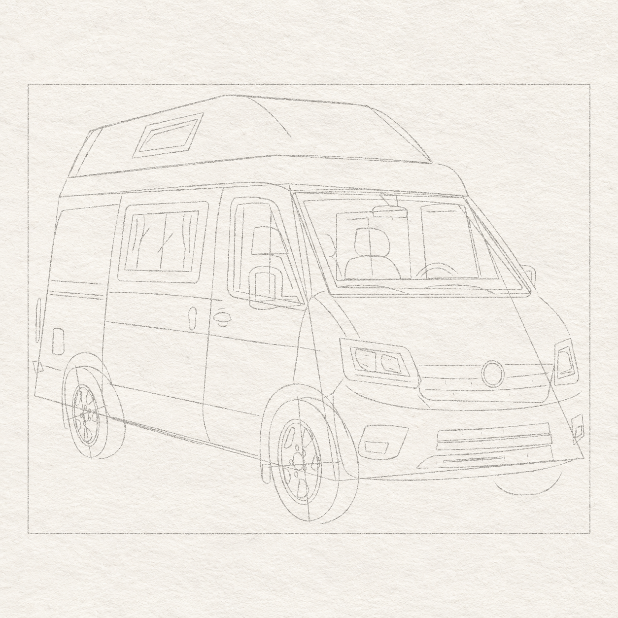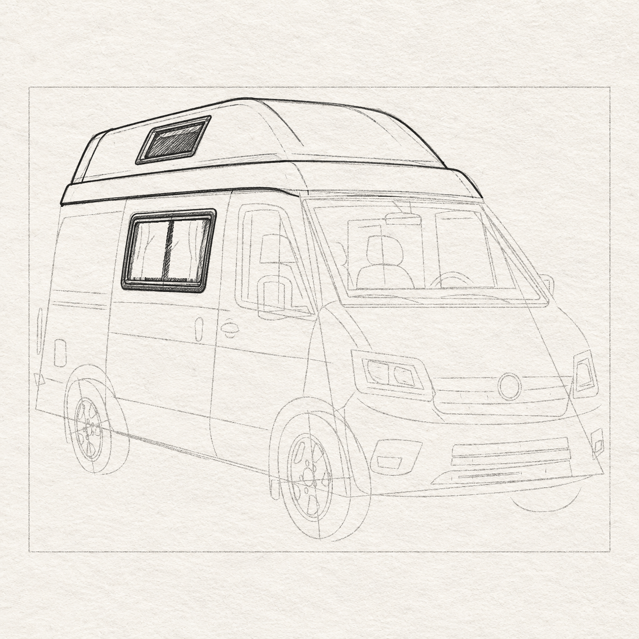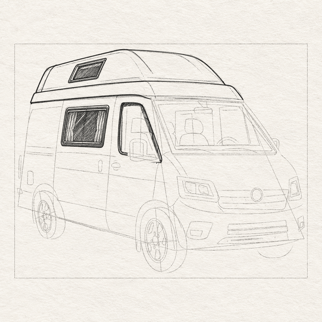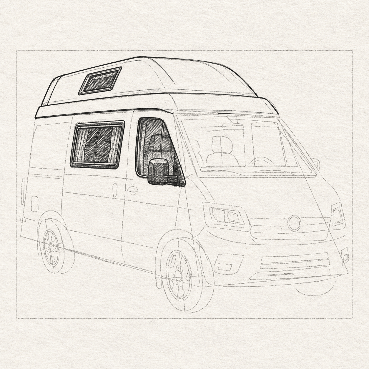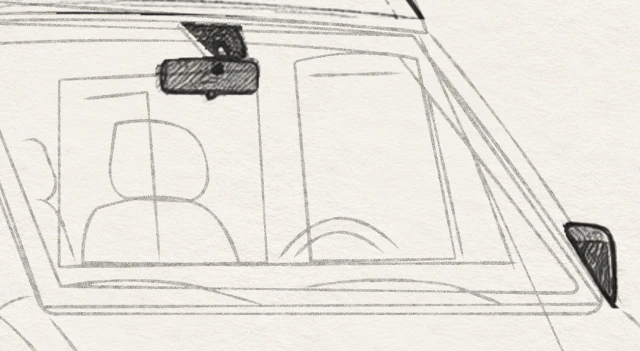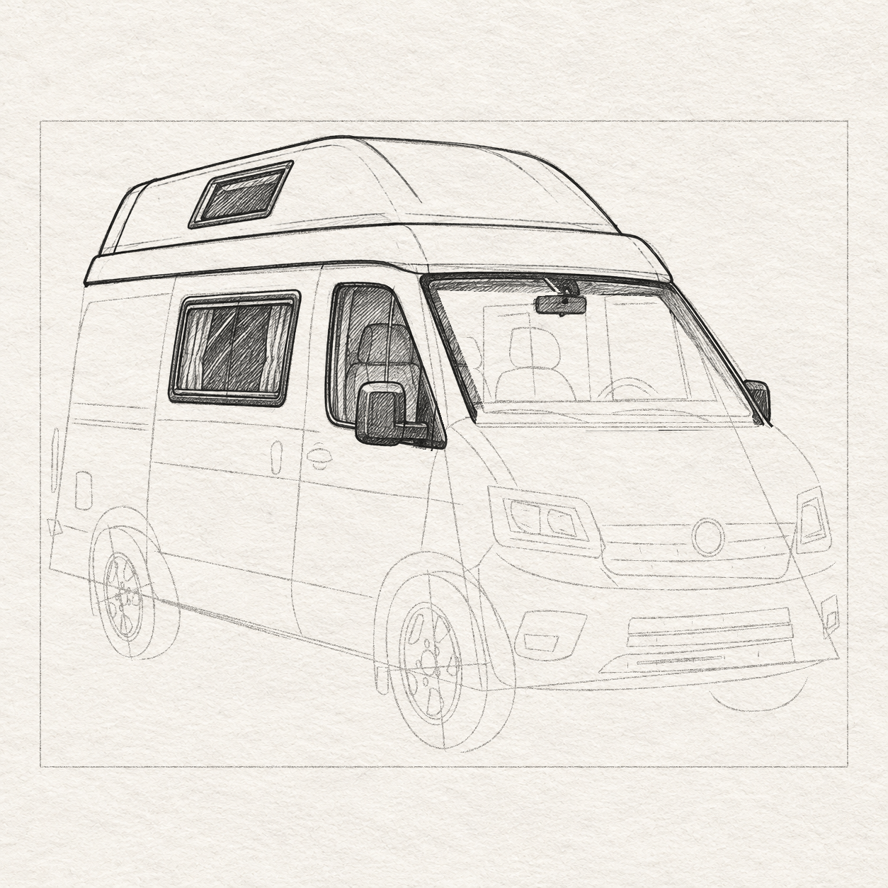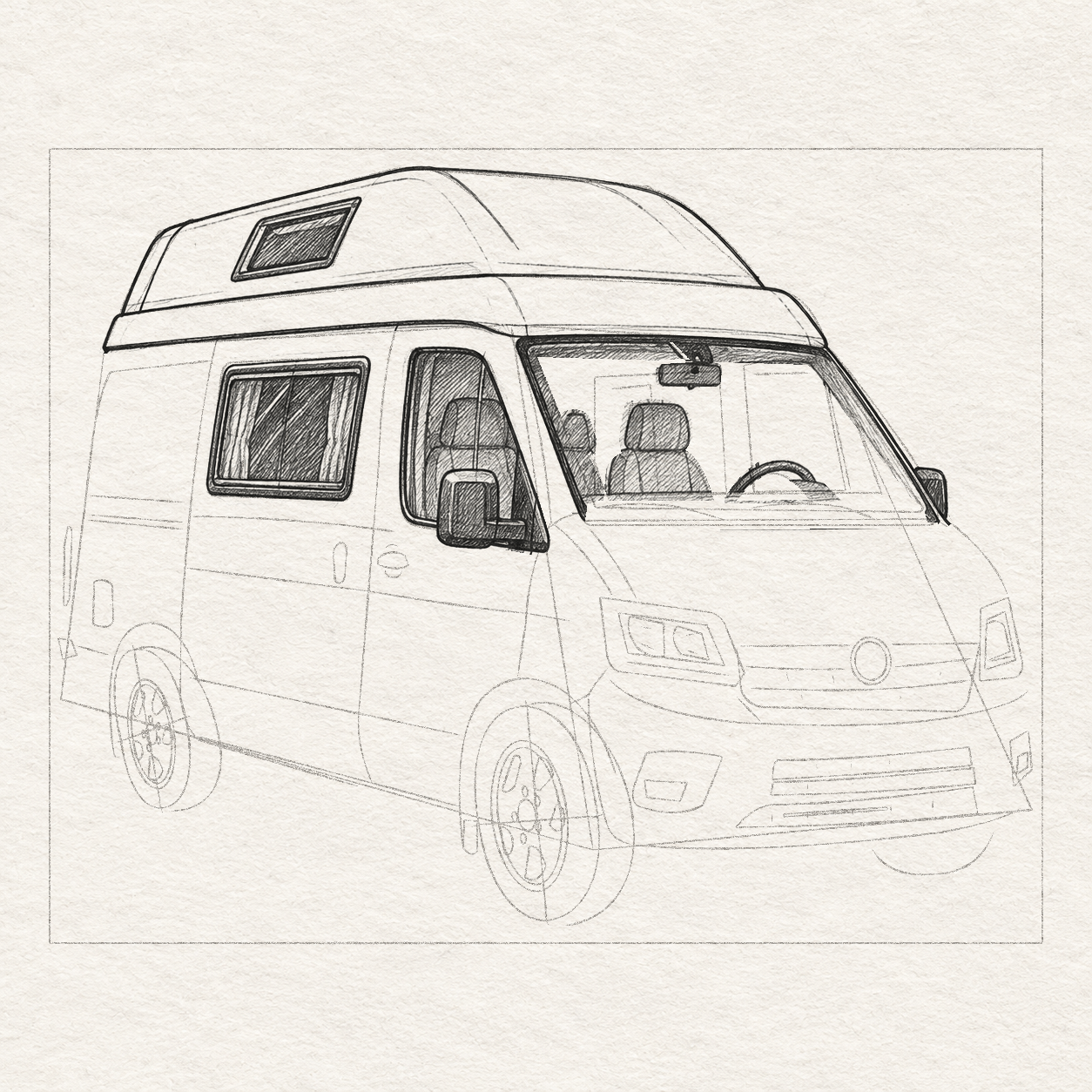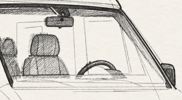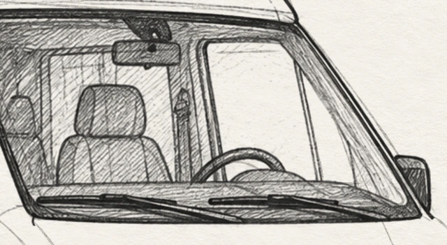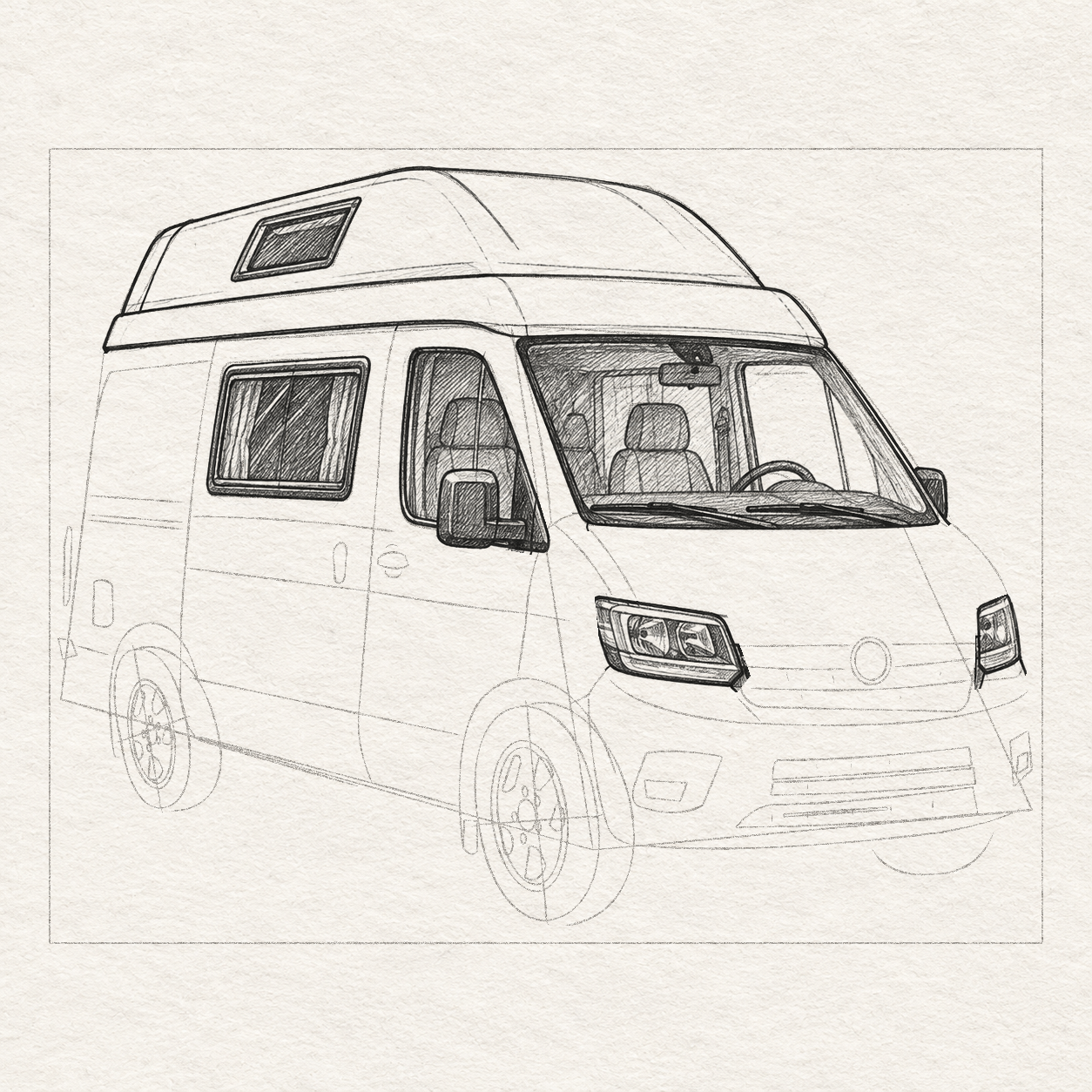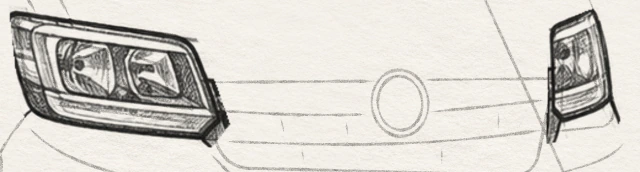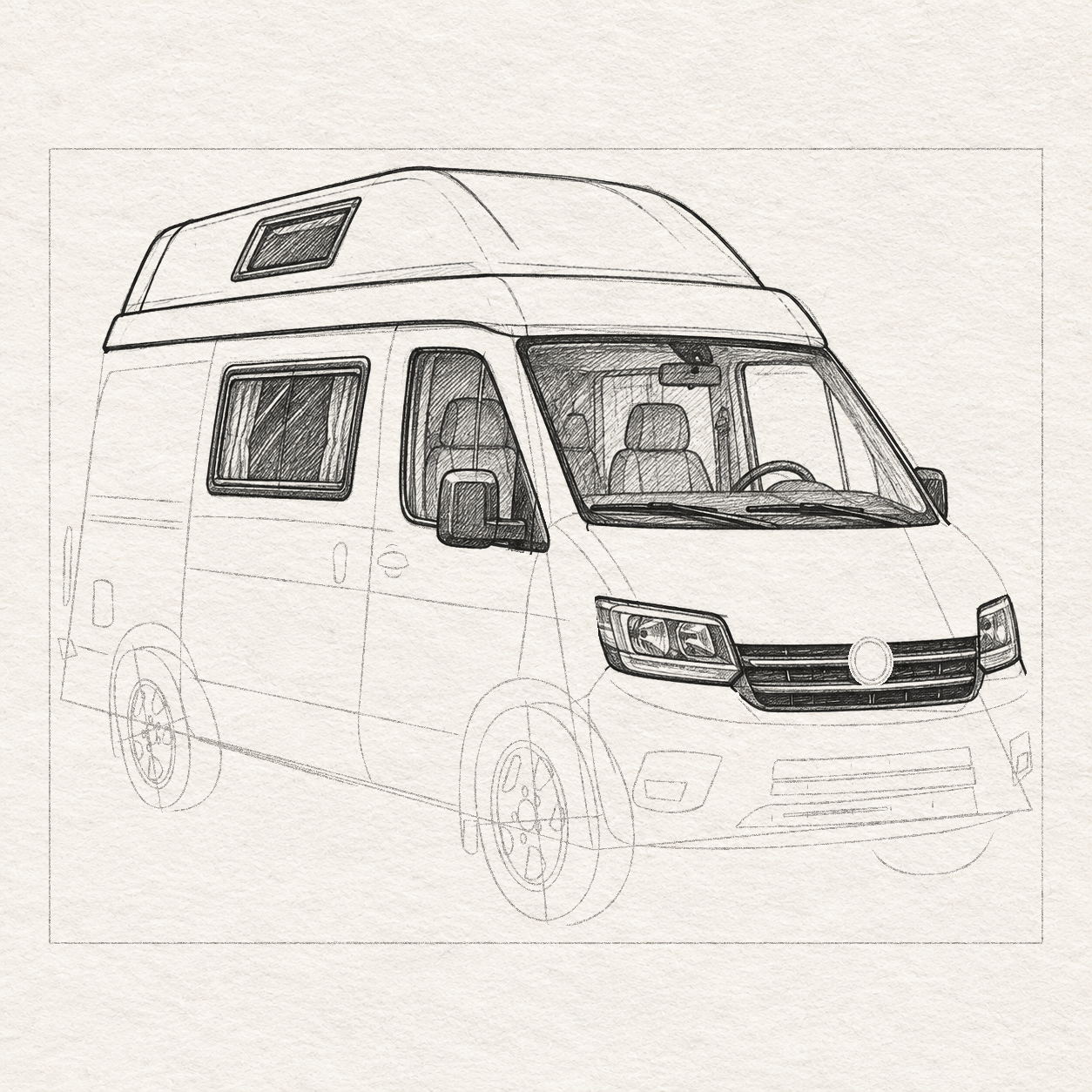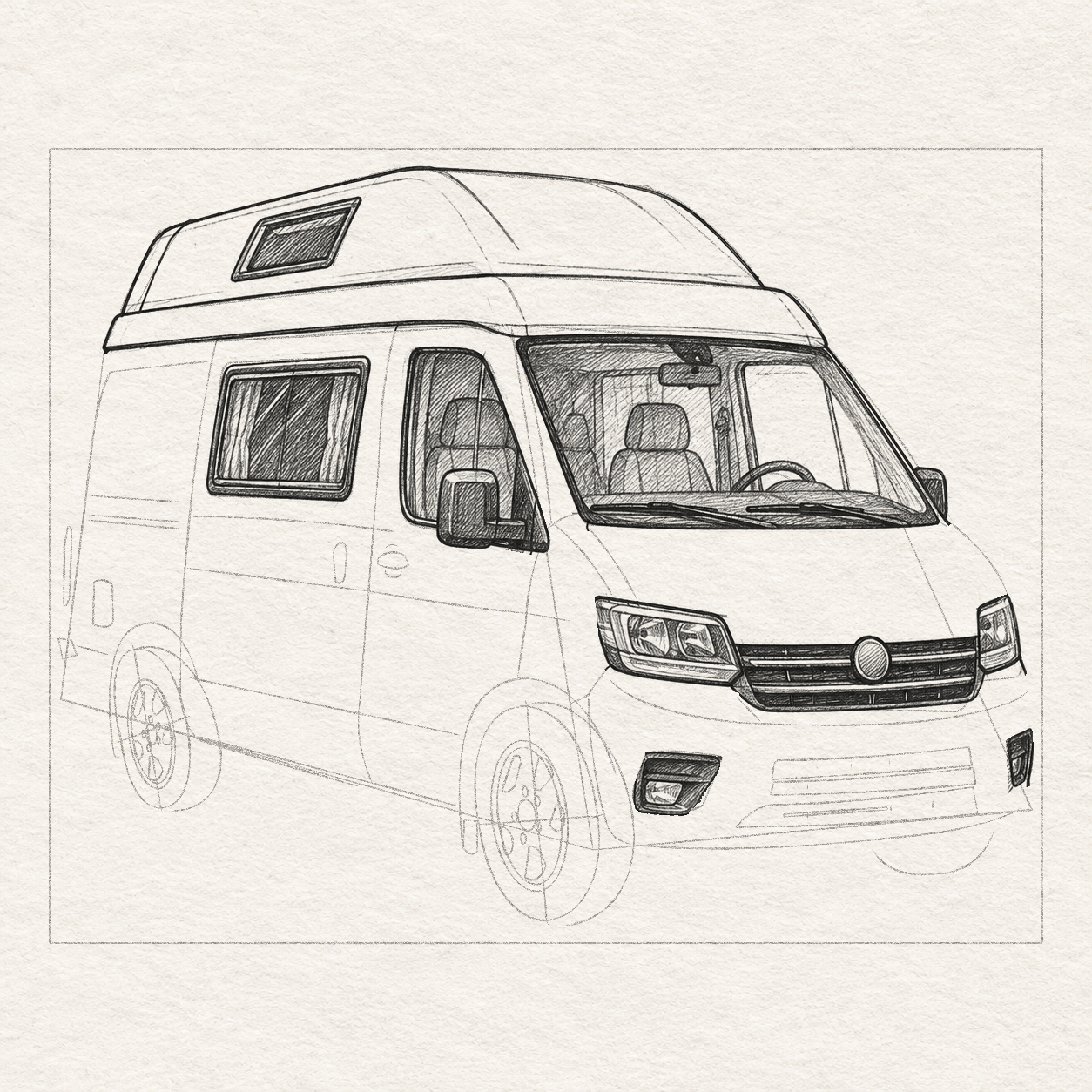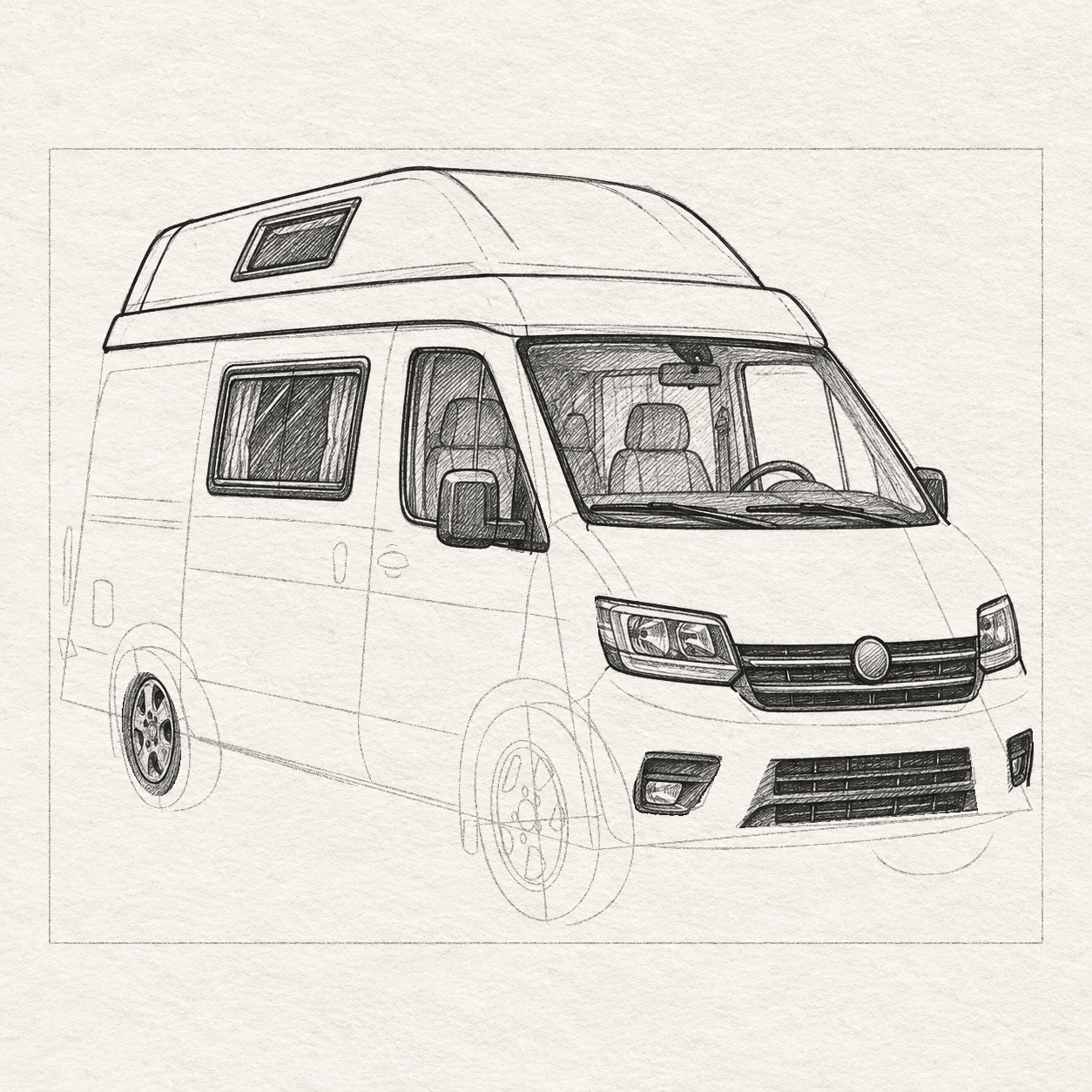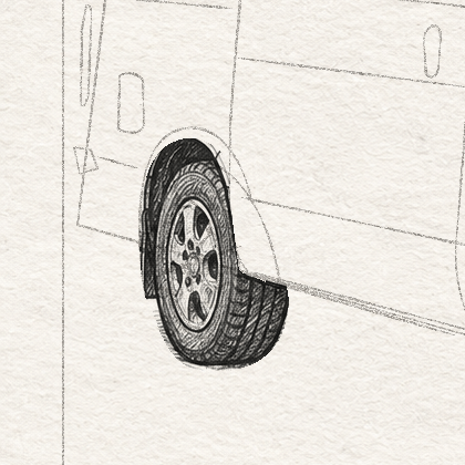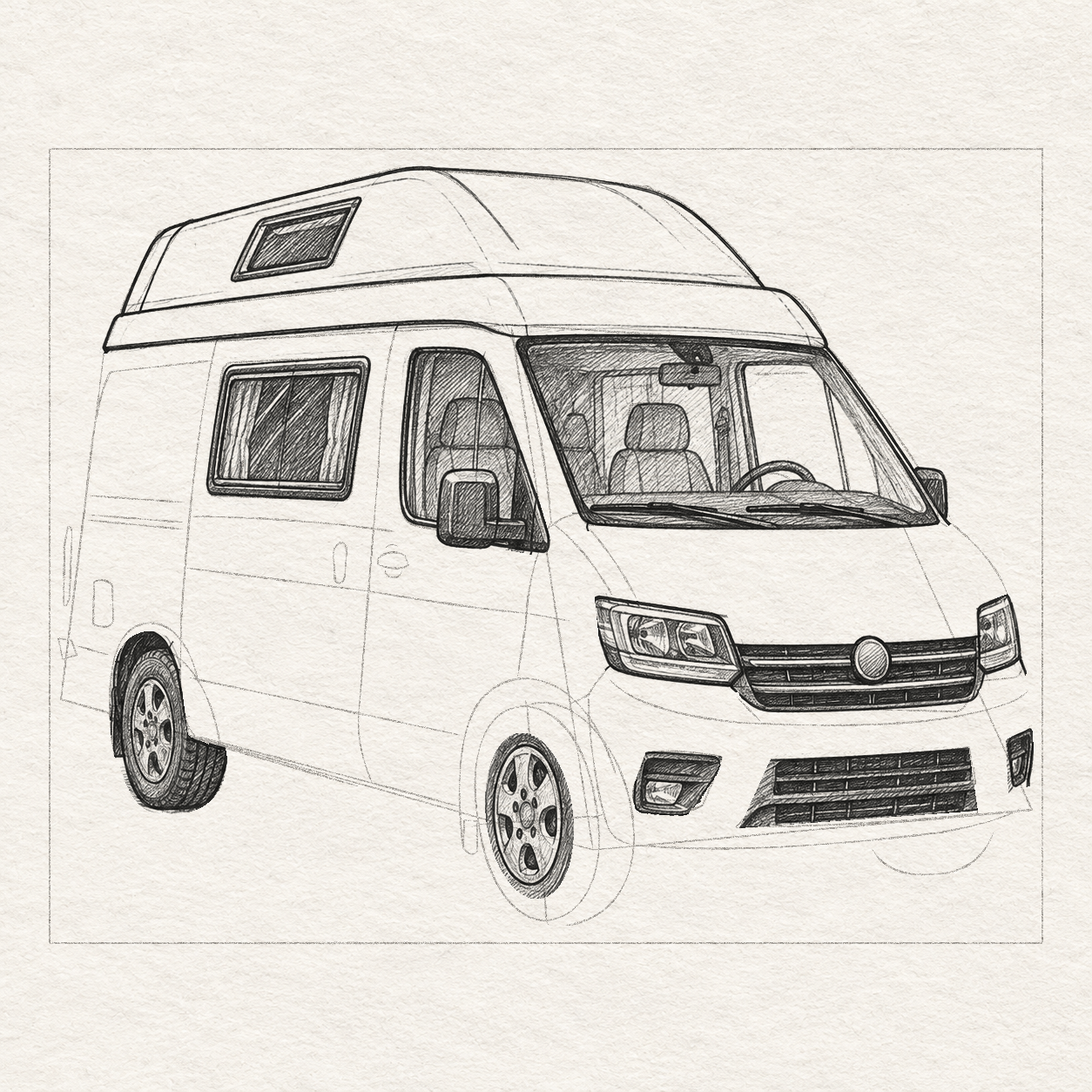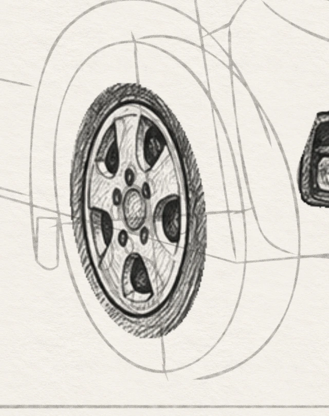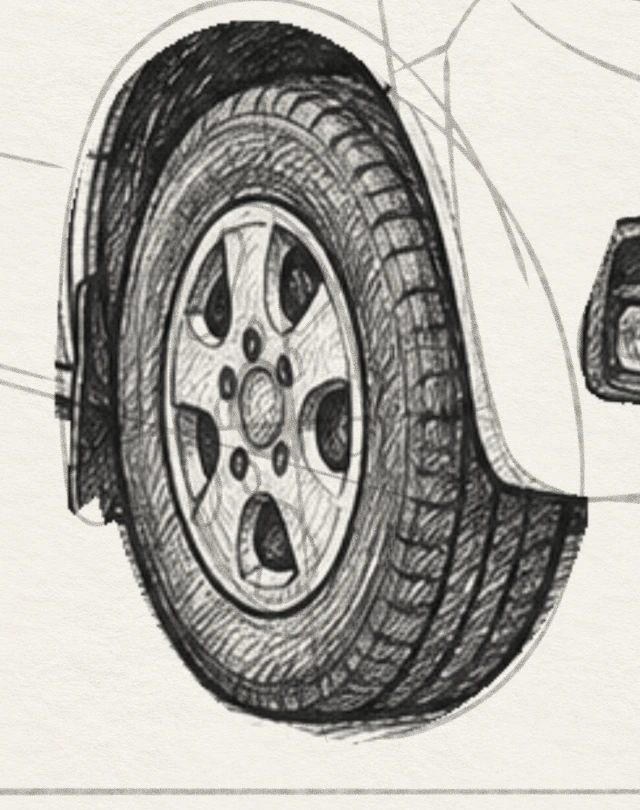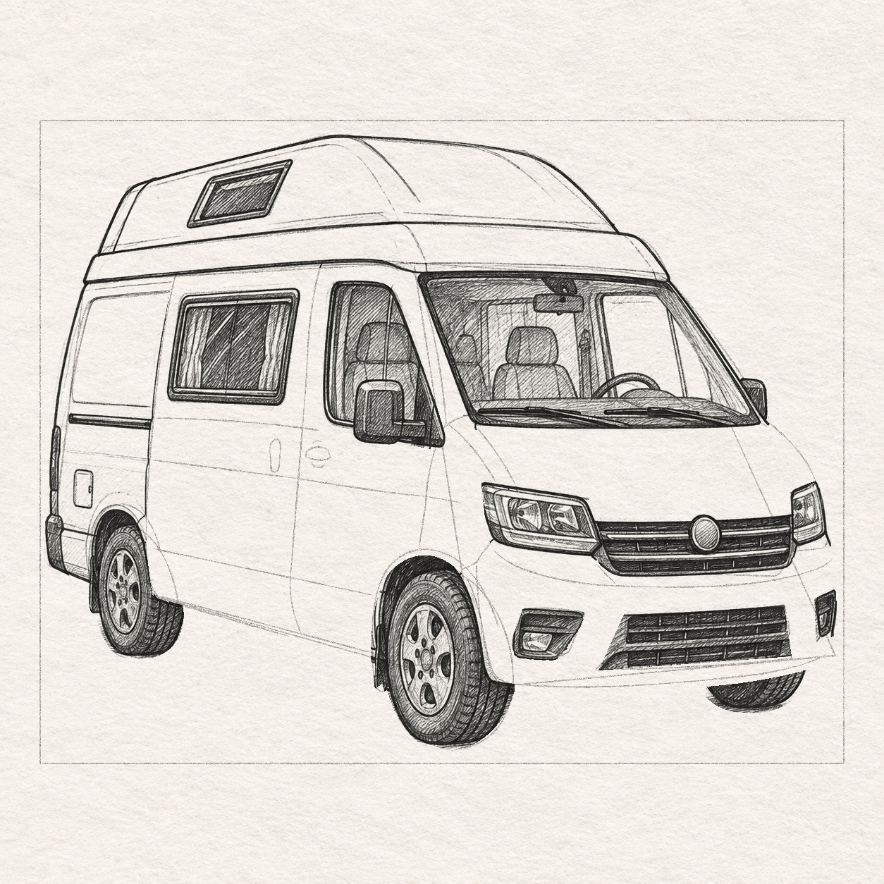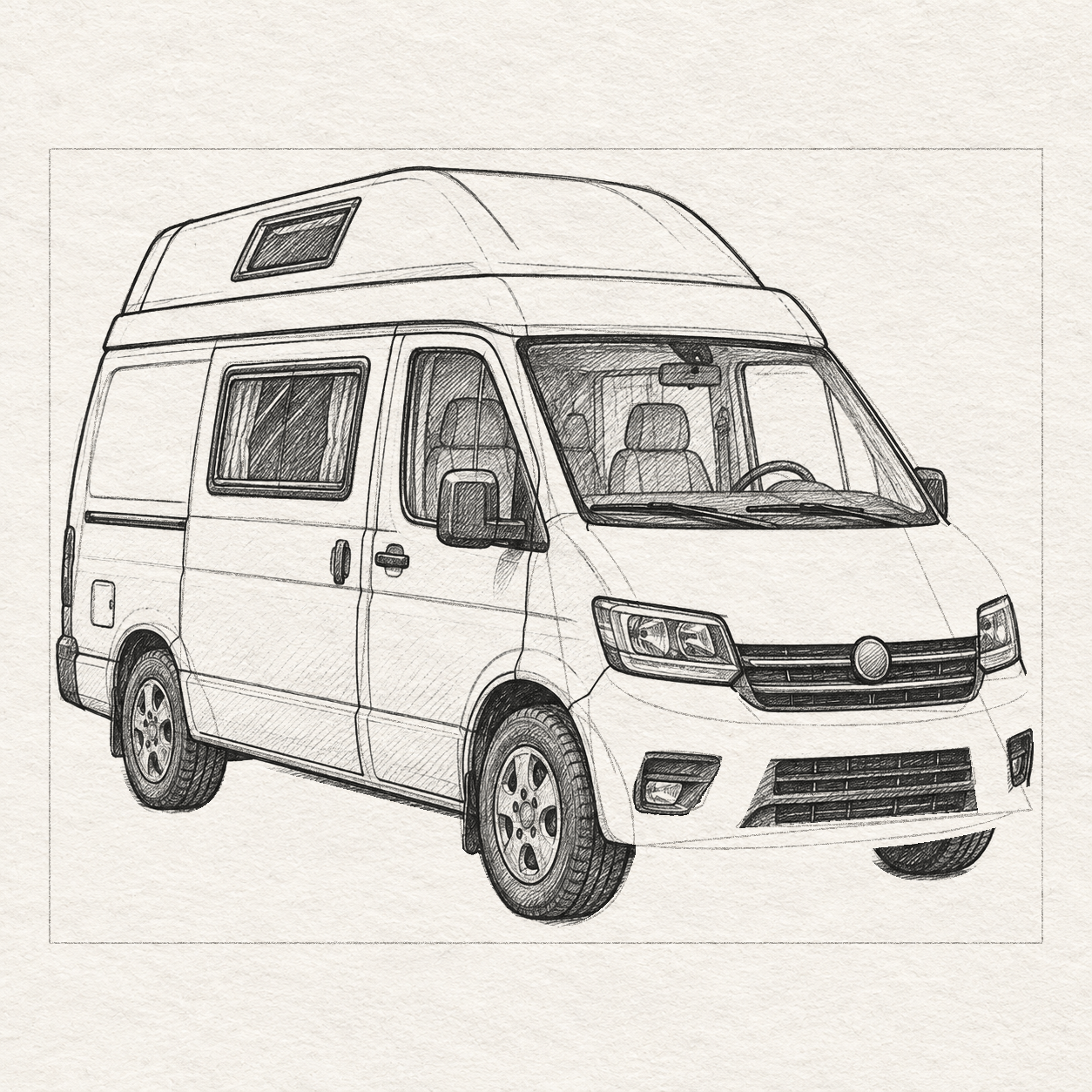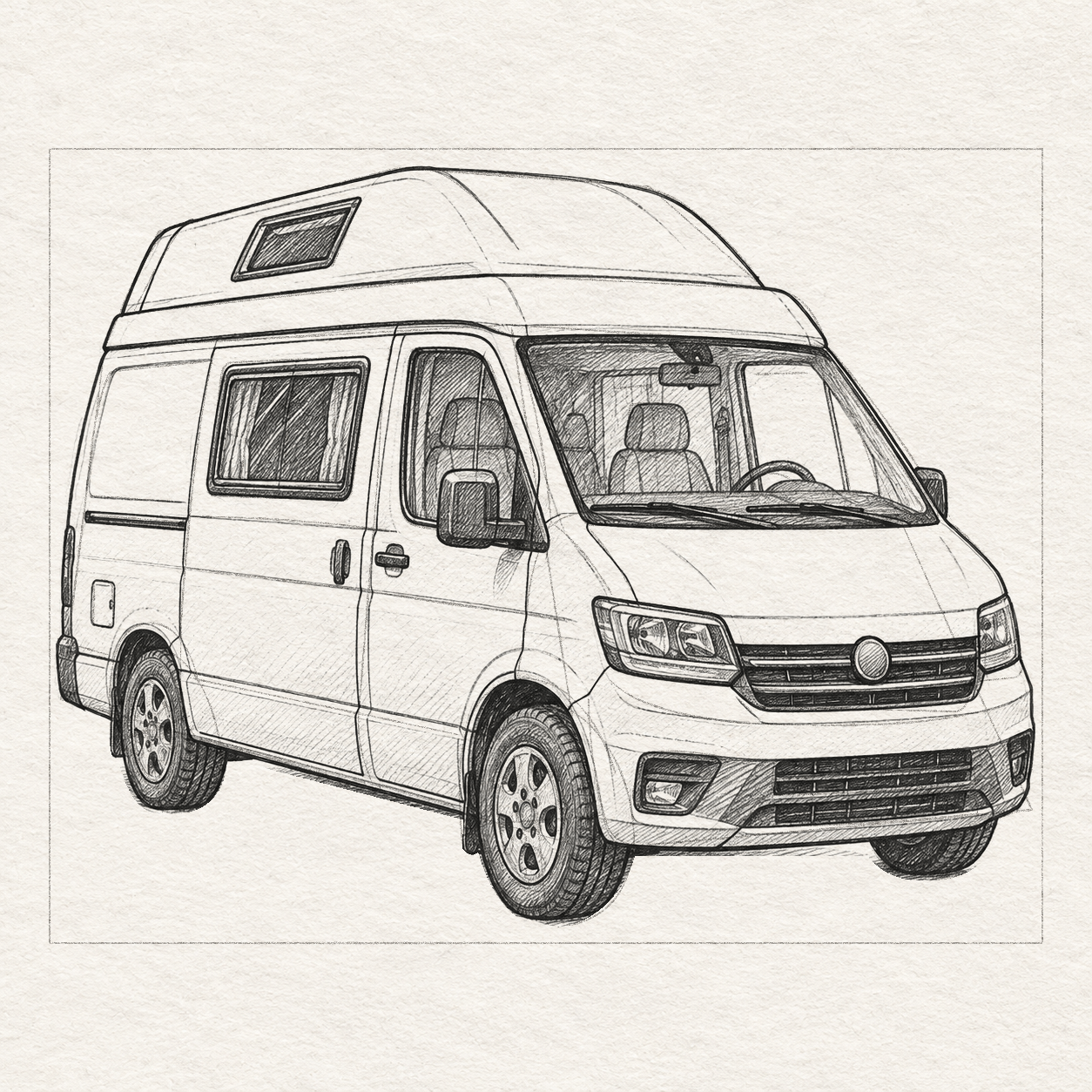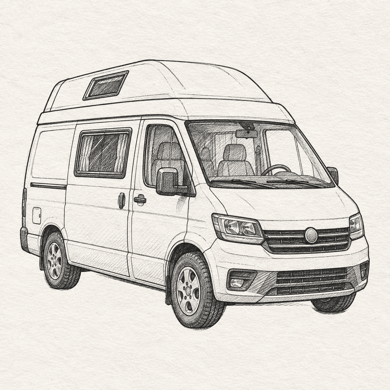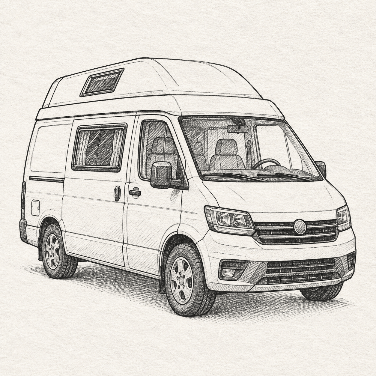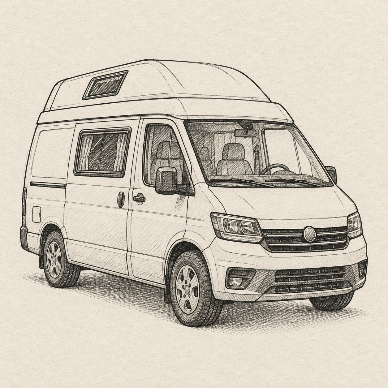
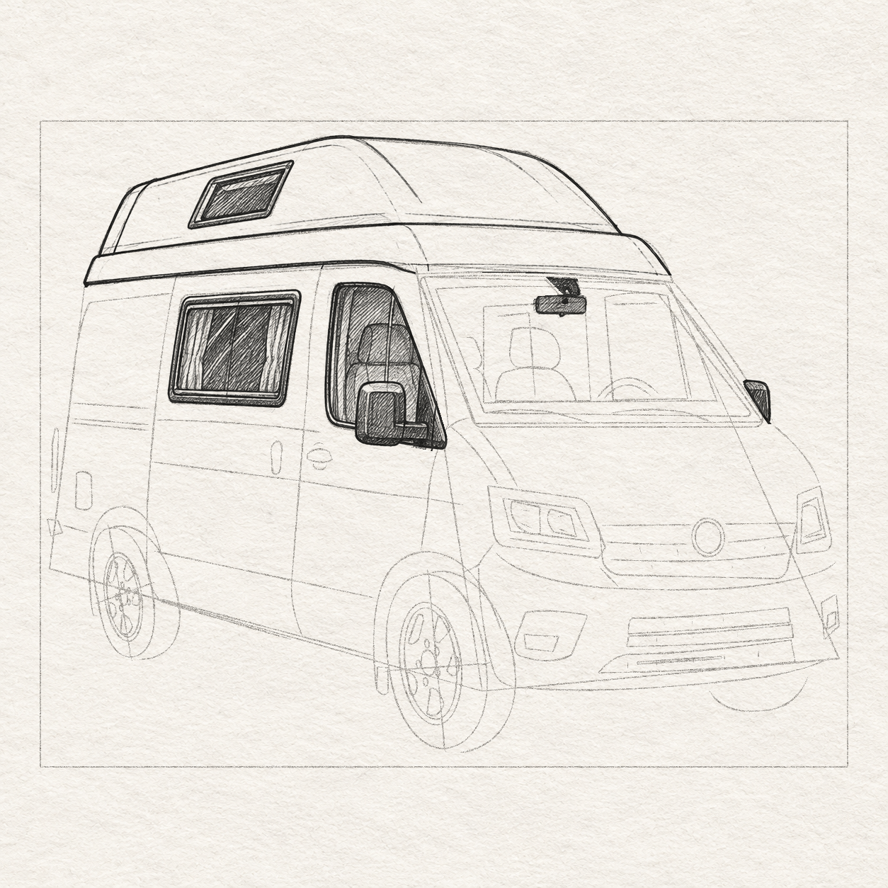
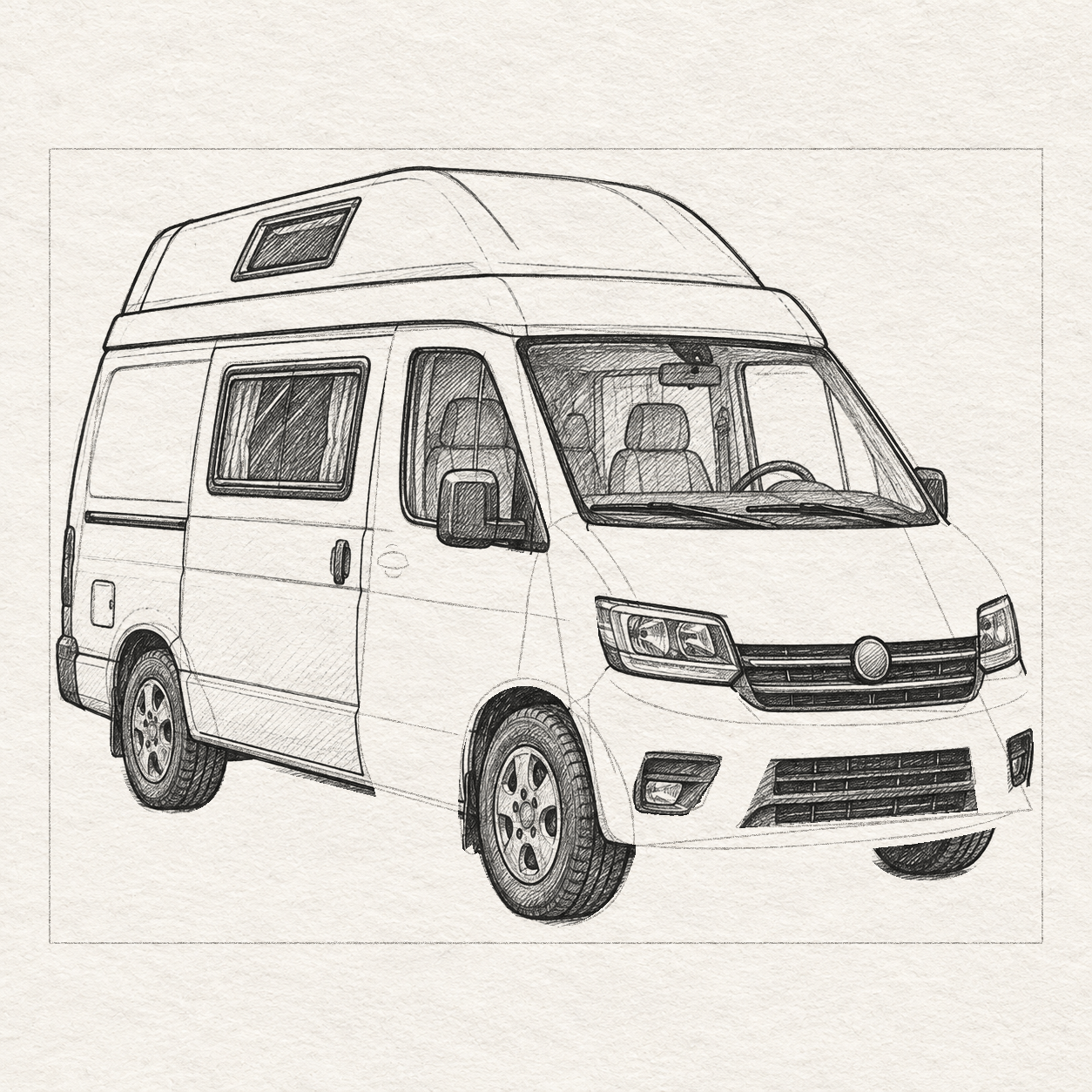
Camper van drawn in black and gray fineliner on pale cream textured sketchbook paper, with a complete silhouette and open margins.
Drawing referenceAbout reference use

Camper van fine ink study

One compact camper van in three-quarter view, rounded box body, front windscreen, side window and visible wheels with natural overlap. Practice form, overlap and selective shading in fine ink.

Things that moveMediumFinelinerReference practice: about 45 min
Save reference

Follow the drawing tutorial

Build this three-quarter camper van from measured pencil planes, then draw its windows, wheels and small fittings before controlled fineliner hatching.

Start the 38-step tutorial

A small thing to tryAlign the wheel bottoms on the same ground plane.

Draw it, one step at a time

How to draw this camper van in fineliner

Build this three-quarter camper van from measured pencil planes, then draw its windows, wheels and small fittings before controlled fineliner hatching.

38 steps · 7 chapters · 66 progress drawings Full tutorial: about 150 minutes, at your pace

What you’ll need

  • HB pencil
  • Soft eraser
  • Ruler marked in centimetres and millimetres
  • Fine black fineliners, about 0.1 and 0.3 mm
  • Sketchbook paper
  • Scrap paper for pen and dry tests

Before you start

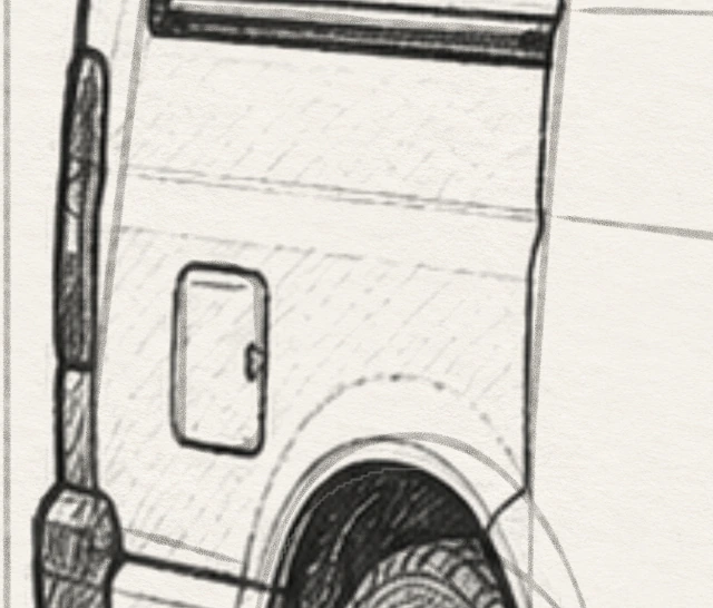
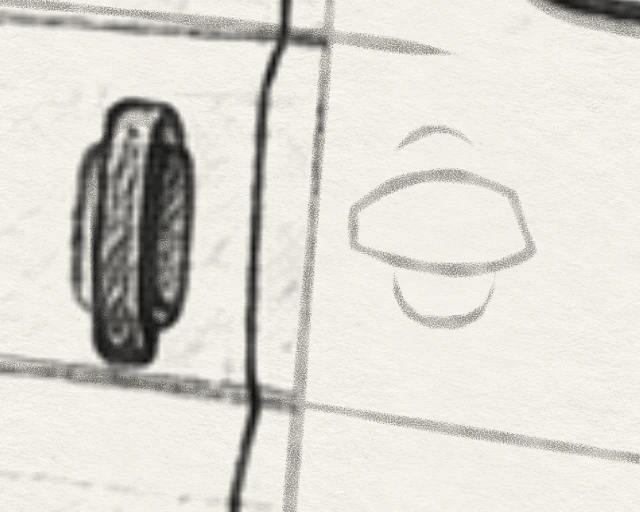
Use paper large enough for a 20 × 16 cm working box with at least 1 cm of clear paper around it. Choose where the box goes; centring is optional. Measure across from the box’s left edge and down from its top unless another mark is named. Left and right mean the sides of the picture. Use a ruler for straight guides and draw curves freehand. The bonnet is the front panel below the windscreen. Keep guides light. For another size, keep all distances in the same proportion.

Each numbered step is one drawing task. Follow its A/B/C drawings and continuous action numbers in order. Take a break between steps or chapters whenever you need one.

Chapter 1 — Build the van and tyres

4 steps · 8 progress drawings · Pencil
  1. Step 1 of 38 · Pencil

    Set the scale and block in the van

    In this example, a light working rectangle sits on textured paper, with a 20 cm width and 16 cm height.
    Drawing 1A — Fit the van on the pageView larger

    Instructions for Drawing 1A — Fit the van on the page
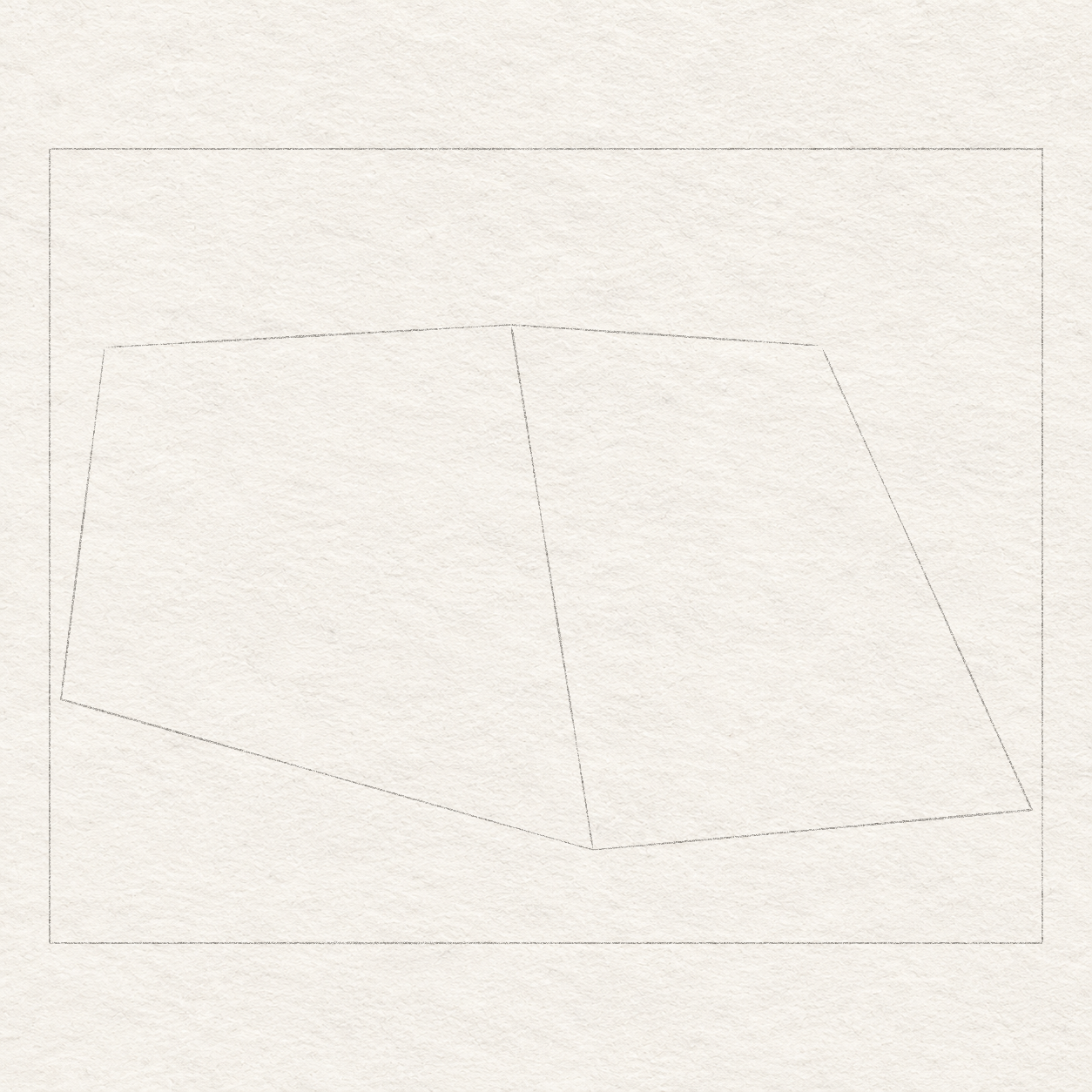
    1. Choose where you want the 20 × 16 cm working box, leaving at least 1 cm of clear paper on every side.
    2. With a ruler and light pencil, draw a 20 cm horizontal top edge. From each end, draw a 16 cm side straight down, then join their lower ends to complete the temporary working box.
    3. For every position, measure across from the guide box’s left edge, then down from its top. All measurements are approximate; a few millimetres of variation is fine. Mark a light dot for a point. When asked to draw a line, use the named start and end. A marked scrap strip is enough; no full grid is needed.
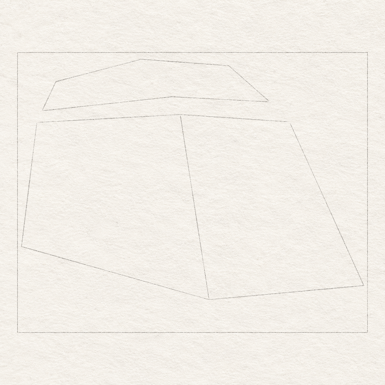
    Two adjoining sloped outlines locate the camper van’s long left side and its right-facing front within the working box.
    Drawing 1B — Mark the side and front facesView larger

    Instructions for Drawing 1B — Mark the side and front faces

    1. Mark the roof points: rear 1.1 cm across and 4 cm down, side/front join 9.3 cm across and 3.5 cm down, and front 15.5 cm across and 4 cm down.
    2. Mark the lower corners: rear 0.25 cm across and 11.1 cm down, nearest front 11 cm across and 14.1 cm down, and far front 19.8 cm across and 13.3 cm down.
    3. Join the three roof dots from rear to side/front join to front. Join the three lower dots from rear to nearest front to far front. Then connect each roof dot to its matching lower dot. The long side is on the left; the front faces right.
    4. Keep these lines light: the side/front join locates the cab, not a permanent seam. If the front looks as wide as the long side, adjust its corners now.
    Next step — Locate and round the raised roof
  2. Step 2 of 38 · Pencil

    Locate and round the raised roof

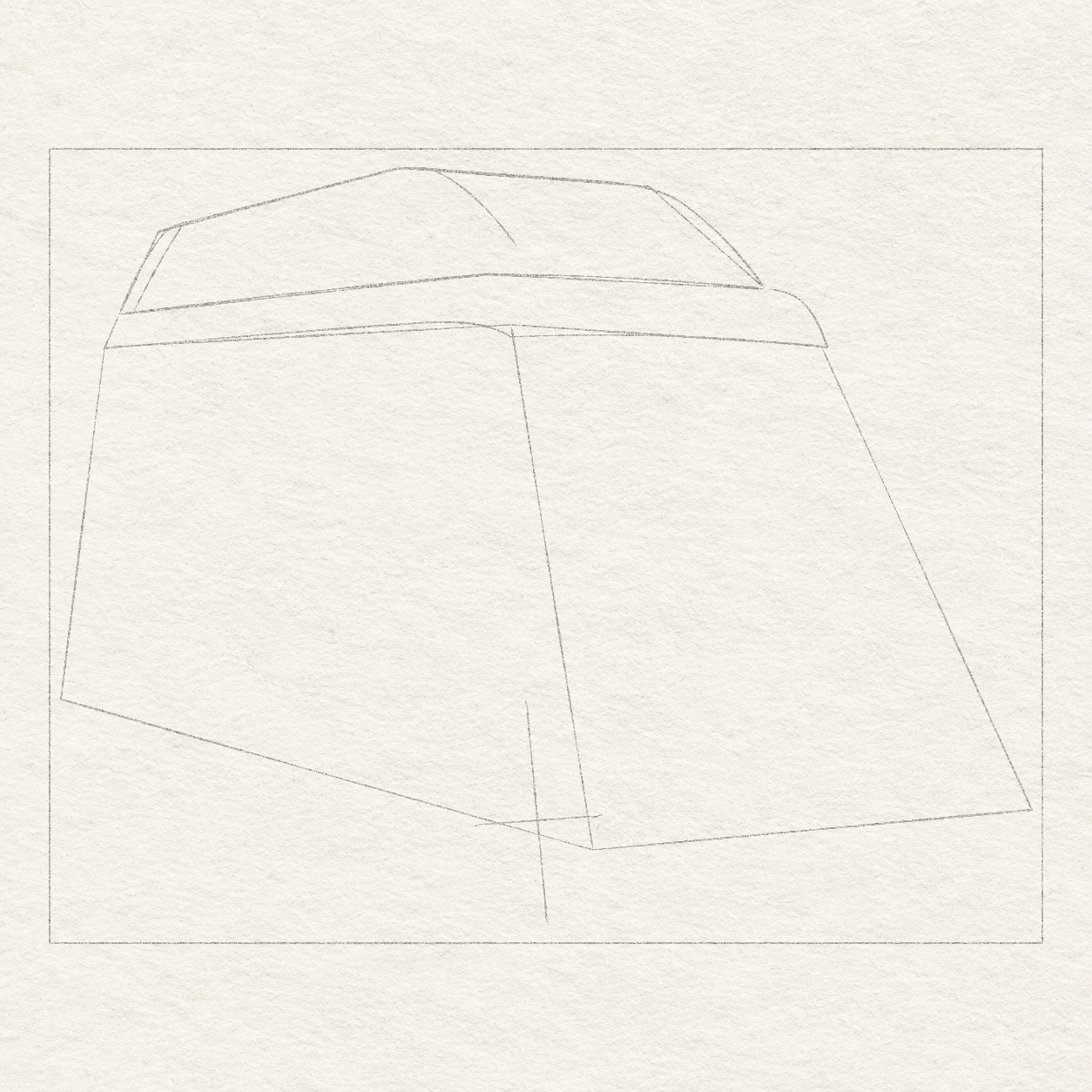
    Straight light segments bound the raised camper roof above the body, with its highest bend left of the side-to-front break.
    Drawing 2A — Locate the raised roofView larger

    Instructions for Drawing 2A — Locate the raised roof
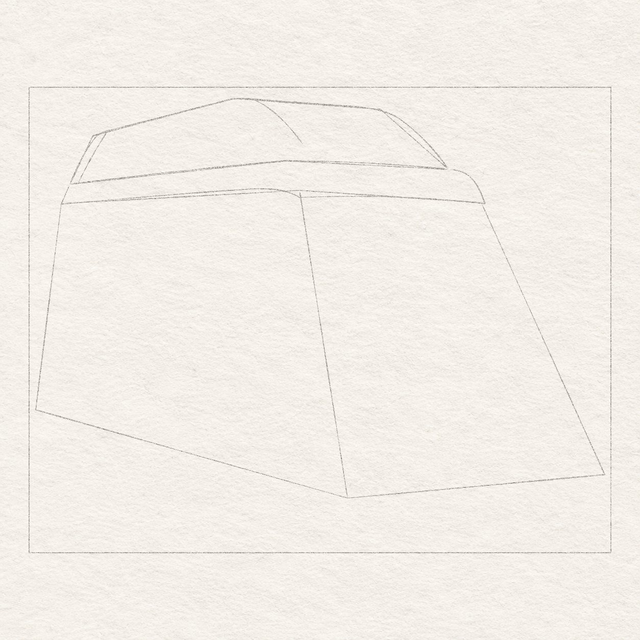
    1. Mark the roof’s rear base at 1.4 cm across and 3.3 cm down and its rear bend at 2.2 cm across and 1.7 cm down.
    2. Mark the highest bend at 7.1 cm across and 0.4 cm down and the front bend at 12.1 cm across and 0.75 cm down.
    3. Mark the front base at 14.4 cm across and 2.8 cm down. Join these points with light straight lines; they locate the rounded roof edge in Drawing 2B.
    4. Join the base points through 8.8 cm across and 2.5 cm down, leaving a broad band below this shallow peak and above the earlier roof line.
    5. The highest point is left of the side/front join; the front base stops before the right roof corner. Do not centre a rectangular roof on the body.
    Rounded roof curves replace the angular envelope as selected contours; a broad lower band and a short cap-turn accent are added.
    Drawing 2B — the roof curves and bandView larger

    Instructions for Drawing 2B — the roof curves and band

    1. Around the straight guide, freehand a gentle curve: bow the top gently, round the rear bend and curve the front cap into its fixed base. Keep both bases fixed; erase a bulging pencil curve instead of thickening it.
    2. Freehand a shallow curve through the lower guide. From its rear base, drop to the rear roof dot. For the lower edge, follow the old roof line closely, adding a shallow downward dip just below the side/front join’s roof dot. Continue to the front roof dot, then curve back up-left to the raised roof’s front base.
    3. Freehand the short cap curve from about 7.5 cm across and 0.4 cm down to 9.4 cm across and 1.9 cm down. Stop about ½ cm above the lower base, without joining the band.
    4. Inside the rear edge, freehand a curve down-left from 2.7 cm across and 1.5 cm down to 1.7 cm across and 3.3 cm down. Leave about ¼ cm between its lower end and the outside roof edge.
    Next step — Shape the large near tyre
  3. Step 3 of 38 · Pencil

    Shape the large near tyre

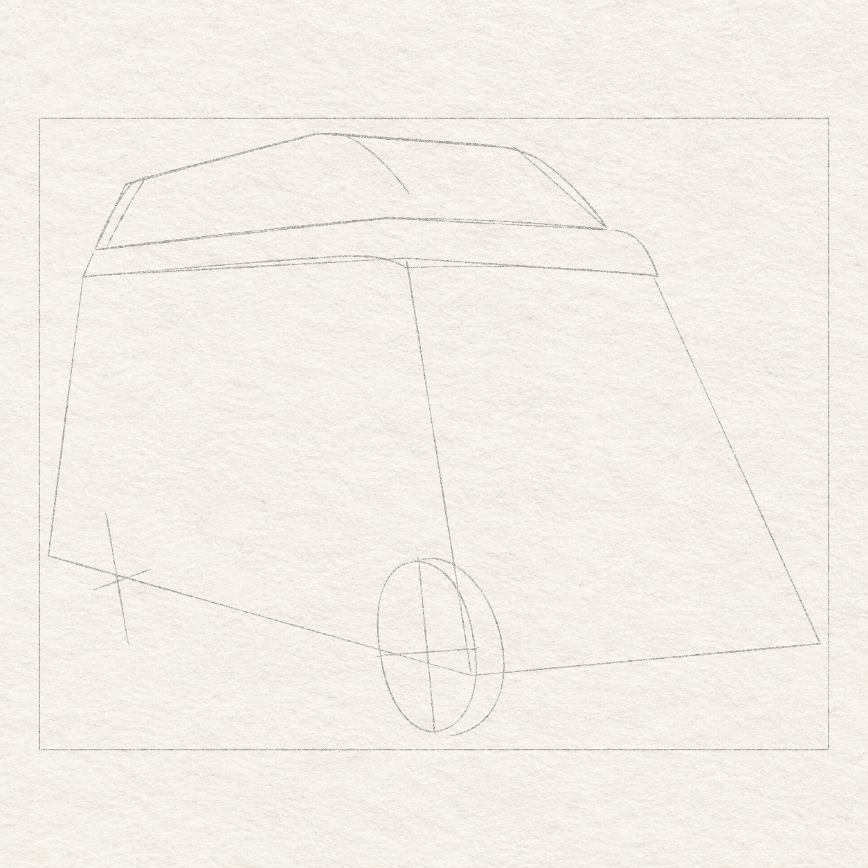
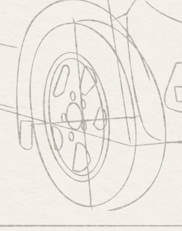
    Four light tips and two crossing diameter directions locate the larger near wheel below the side-to-front body corner.
    Drawing 3A — Mark the large wheel’s four endsView larger

    Instructions for Drawing 3A — Mark the large wheel’s four ends
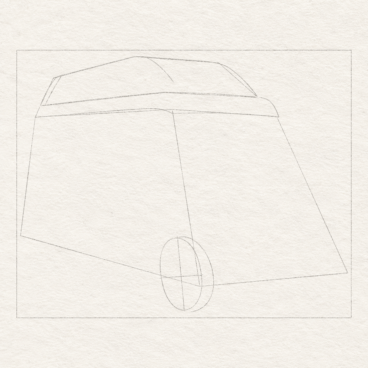
    1. Mark the large wheel’s top 9.6 cm across and 11.25 cm down, bottom 9.9 cm across and 15.55 cm down, left 8.6 cm across and 13.45 cm down, and right 11.1 cm across and 13.2 cm down. Join opposite ends lightly: the long line leans down-right and the short line rises slightly right.
    2. Its bottom reaches below the nearest lower body corner; its width is about half its height. Correct any misplaced end now, then keep all four ends fixed for Drawing 3B.
    A tall, slightly tilted near tyre face surrounds the wheel tips, with a tapering tread-depth curve on its right.
    Drawing 3B — the near tyre and its depthView larger

    Instructions for Drawing 3B — the near tyre and its depth

    1. Rehearse the oval above those four marks before touching the page. Freehand the oval through them lightly, making the top a little fuller and the bottom slightly flatter. Keep the established contact height.
    2. Freehand the tread’s curved right edge, about ½ cm from the face at its widest point. Taper this strip into the face at top and bottom; leave the face on its left, rather than drawing a second complete wheel.
    Next step — Shape the rear tyre and exposed far arc
  4. Step 4 of 38 · Pencil

    Shape the rear tyre and exposed far arc

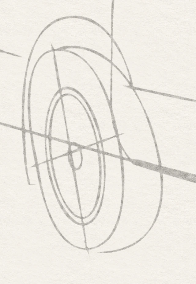
    Four tips and crossing diameter directions locate the smaller rear wheel higher and farther left than the near wheel.
    Drawing 4A — Mark the small wheel’s four endsView larger

    Instructions for Drawing 4A — Mark the small wheel’s four ends
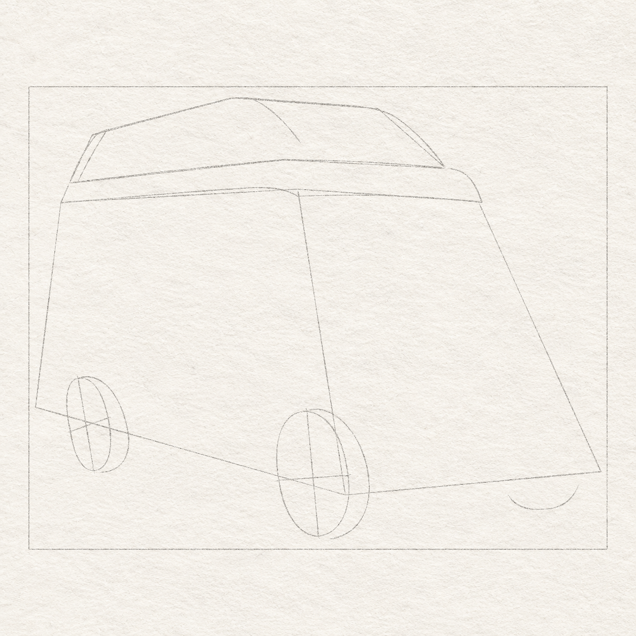
    1. Mark the rear wheel’s top 1.7 cm across and 10 cm down, bottom 2.25 cm across and 13.3 cm down, left 1.45 cm across and 11.95 cm down, and right 2.75 cm across and 11.45 cm down. Join opposite ends lightly; its long line also leans down-right.
    2. Its face is about 1.3 cm wide, compared with 2.5 for the near wheel before tread. Keep this wheel higher on the page, not on the same bottom line. Move all four marks together if its position is wrong.
    The smaller rear tyre is rounded with a right depth return, while a separate shallow far-tyre arc sits below the front-plane bound.
    Drawing 4B — Round the rear tyre and far visible arcView larger

    Instructions for Drawing 4B — Round the rear tyre and far visible arc

    1. Freehand the rear tyre through its four ends. Add a freehand right-hand tread strip about ½ cm wide at its middle, tapering into the face at both ends. Keep its hidden upper section light: it is not an ink line through the side panel.
    2. Under the far front, mark 16.5 cm across and 14.1 cm down, dip through 17.75 cm across and 14.6 cm down, then freehand the shallow curve up-right to 19 cm across and 13.7 cm down. The ends sit below the straight front-body guide: left about ½ cm and right about ⅓ cm.
    3. Keep just that shallow exposed arc. The later bumper will cover its ends; there is no bumper edge to trace yet.
    Next step — Place and frame the windscreen

Chapter 2 — Draw the windows and body panels

6 steps · 9 progress drawings · Pencil
  1. Step 5 of 38 · Pencil

    Place and frame the windscreen

    A four-corner windscreen guide is added to the front plane, narrow at its top and wider at its lower edge.
    Drawing 5A — the windscreen quadrilateralView larger

    Instructions for Drawing 5A — the windscreen quadrilateral
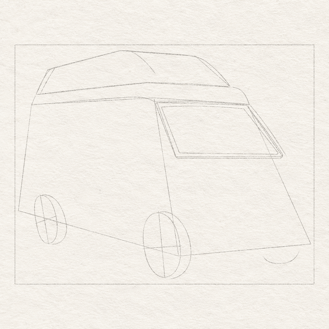
    1. Mark the windscreen corners clockwise: upper-left 9.5 cm across and 3.9 cm down, upper-right 15.5 cm across and 4 cm down, lower-right 17.9 cm across and 7.45 cm down, lower-left 10.8 cm across and 7.5 cm down. Join lightly; both sides lean down-right and the bottom is wider than the top.
    2. Leave a narrow painted pillar on the left, between glass and side/front guide. Keep the bottom above the future bonnet. Adjust individual corners before rounding the frame in Drawing 5B.
    Rounded outer and inner windscreen contours reserve a seal band, with a separate outside edge for the narrow right painted pillar.
    Drawing 5B — the windscreen sealView larger

    Instructions for Drawing 5B — the windscreen seal

    1. Freehand the rounded glass corners and gently bowed long sides. Add an inner line about ¼ cm inside the top and left edges, slightly less inside the right.
    2. Freehand the inner bottom edge, leaving a seal a little wider than ¼ cm at the bottom, with room above it for the later wipers. Keep the frame continuous; reopen a closing band by erasing its inner line without moving the whole pane.
    3. Outside the right glass edge, leave a painted pillar about ¼ cm wide, tapering toward the roof. Freehand its outside edge from the roof corner to ¼ cm outside the lower-right glass corner, separate from the glass seal.
    Next step — Draw the side window and curtains
  2. Step 6 of 38 · Pencil

    Draw the side window and curtains

    A rounded side-window frame with an inset lip and sloping central divider is placed on the long side of the camper.
    Drawing 6A — the large side-window frameView larger

    Instructions for Drawing 6A — the large side-window frame
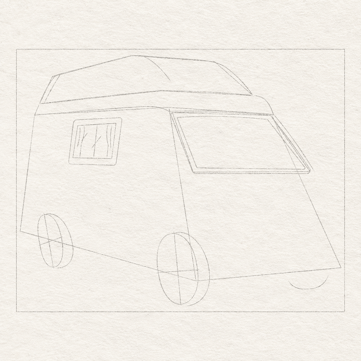
    1. Mark corners 3.55 cm across and 4.35 cm down, 6.35 cm across and 4.2 cm down, 6 cm across and 7.05 cm down, and 3.2 cm across and 7 cm down, then join them freehand in that order with rounded corners. The top rises gently right and the sides lean down-left.
    2. Follow the outer window’s four sides with a second perimeter about ¼ cm inside. Draw it freehand around the rounded corners, keeping every frame band open and bodywork clear above and below. Repair a disappearing band at its inner edge while the pencil is light.
    3. Start the divider slightly right of the inner top’s midpoint and slope down-left to the inner sill. Leave two unequal panes.
    Wavy curtain edges, shorter folds and small bright-gap guides are added inside the two side-window panes.
    Drawing 6B — curtains inside the side windowView larger

    Instructions for Drawing 6B — curtains inside the side window

    1. Start each curtain at the inner top edge, about ½ cm in from the outer side of its pane. Freehand a wavy edge down to the inner bottom edge. Bend the left curtain toward the middle and the right toward the outside.
    2. By eye, add one shorter freehand fold near each outside edge, leaving the divider unchanged and the centre glass clear. No curtain runs down the divider. Soften a rigid-looking curtain curve rather than making another frame bar.
    3. In the clear glass, lightly mark two short down-left lines: one beside the left curtain and one near the divider. These locate narrow bright stripes to leave unshaded later; their exact positions may vary.
    Next step — Place the cab and roof windows
  3. Step 7 of 38 · Pencil

    Place the cab and roof windows

    A tall raked cab pane, its inset frame and two nearly upright glazing divisions are drawn beside the windscreen pillar.
    Drawing 7A — the cab-door windowView larger

    Instructions for Drawing 7A — the cab-door window
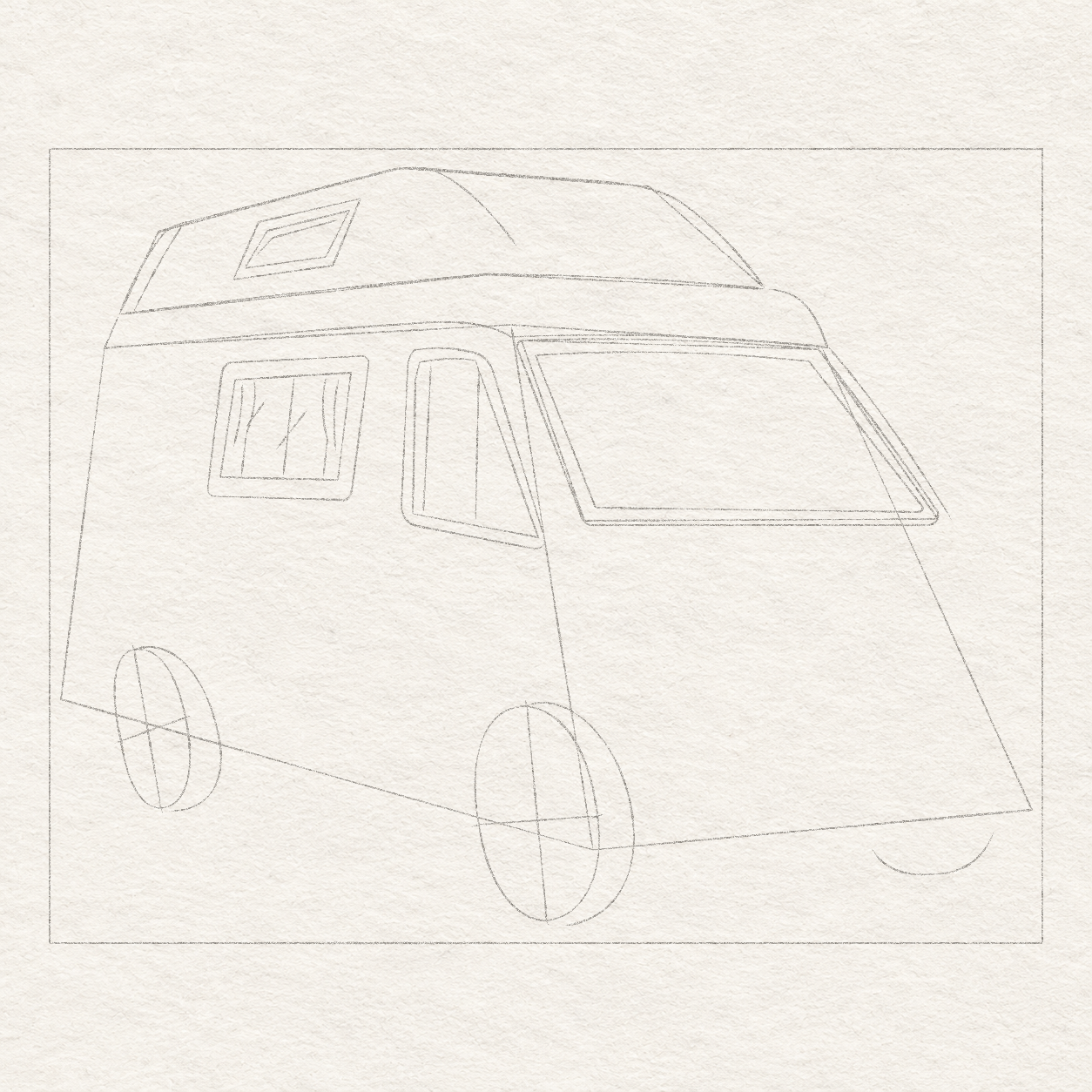
    1. Mark the cab-window corners at 7.35 cm across and 4.05 cm down, 8.6 cm across and 4.1 cm down, 9.9 cm across and 7.9 cm down and 7.1 cm across and 7.5 cm down. Join them freehand with the rounded upper-left corner and steep front edge. Draw a second outline about ¼ cm inside for the glass; keep that frame band open.
    2. About ¼ cm inside the rear glass edge, draw a nearly vertical division from top to sill, leaning slightly down-left.
    3. Start about ¼ cm below the glass’s upper-front corner. Draw the front divider almost straight down to the glass’s bottom edge, leaning only slightly left; it is much more upright than the outside front edge.
    4. Keep the pane tall and narrow. Leave its lower-front guide light where the mirror will later hide it.
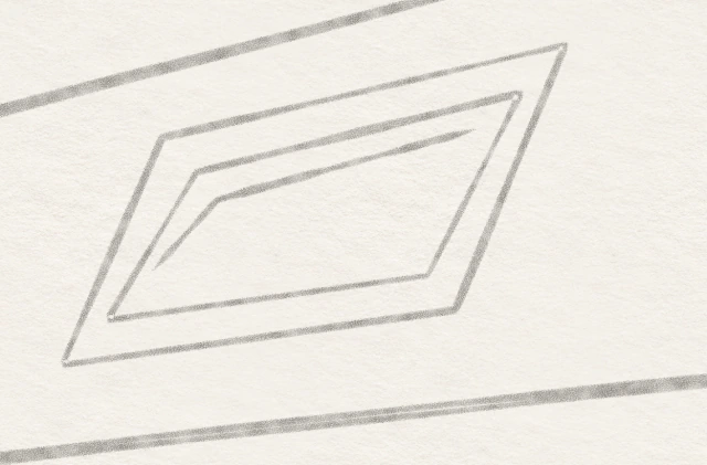
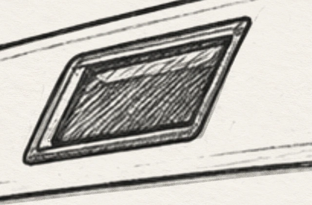
    A small slanted inset window is placed inside the raised roof, with a narrow frame lip and an upper-left bright reserve.
    Drawing 7B — the little roof windowView larger
    Enlarged current pencil roof-window frame, inset glazing and short upper-left bright reserve.
    Detail 7B.1 — Roof windowEnlarged from this same step. Keep the outer frame, inner glazing inset and upper-left bright reserve distinct; these are light locations before pen.

    Instructions for Drawing 7B — the little roof window

    1. Inside the raised roof, join 3.7 cm across and 2.65 cm down, 4.2 cm across and 1.5 cm down, 6.25 cm across and 1 cm down, and 5.7 cm across and 2.35 cm down in that order. Keep it slanted with the roof side, not a level rectangle.
    2. Draw a smaller slanted outline inside the roof window, leaving a narrow frame band. Inside its upper-left, mark a thin bright strip that turns up-right along the top of the glass. Leave this strip and a thin inner frame lip white during shading; their small widths may vary. Keep clear paper between the outside frame and roof outline. If they touch, move the whole window inward while the pencil is light.
    Next step — Locate the door seams and fine body lines
  4. Step 8 of 38 · Pencil

    Locate the door seams and fine body lines

    Door seams, a rear panel inset, a rubbing strip and two fine across-body contours are selected; the upper fine line stops beside the cab pane while the lower continues farther right. A separate light outside cab-door positioning guide starts on the roof band, descends beside the cab frame and continues down-left above the near tyre.
    Drawing 8A — Add the panel outlinesView larger

    Instructions for Drawing 8A — Add the panel outlines

    1. Start just left of the large side window’s upper-left corner, on the roof band. Freehand the rear door seam down-left beside the window to the existing sloping bottom body guide. Round its lower turn to the right along that guide.
    2. Start the front door seam on the roof band in the gap between the large side window and the cab window, about ½ cm left of the cab frame. Freehand a curve down-left to meet the same sloping bottom body guide.
    3. On the roof band, mark a point about 7 mm right and 3 mm above the cab frame’s upper-front corner. Lightly curve down-right to a point about 2 mm right and 3 mm above the turn where its steep front edge meets the sill. This is an outside positioning guide for the cab door, not a glass edge or the final rounded door outline. Keep the gap from the window open.
    4. From the lower end of that new outside guide, beside the cab window’s lower-front corner, curve down-left to 9.4 cm across and 10.7 cm down. Stop about ½ cm above and ¼ cm left of the large tyre’s top; the arch comes next. Keep this lower cab-door guide for the later ink pass.
    5. For the blank rear panel, join corners 1.25 cm across and 4.5 cm down, 0.75 cm across and 7 cm down, 2.8 cm across and 7.1 cm down, and 3.3 cm across and 4.25 cm down. Round the left corners freehand; meet the rear door seam on the right.
    6. Below it, draw two short strip lines ⅛ cm apart. Stop both at the seam.
    7. Add a fine upper body line from 2.8 cm across and 7.4 cm down, through 6.5 cm across and 7.65 cm down, to 7 cm across and 7.7 cm down. Stop just left of the cab pane.
    8. Add the lower fine line from 2.7 cm across and 8.45 cm down, through 6.45 cm across and 8.9 cm down and 9.6 cm across and 9.35 cm down, to 10.6 cm across and 9.5 cm down. This one continues across the cab seam.
    9. Keep seams outside the windows and both fine lines at their separate endpoints. Correct the new line, rather than moving a window to fit it.
    Next step — Shape the arches and lower sill
  5. Step 9 of 38 · Pencil

    Shape the arches and lower sill

    Broader body arches surround the two tyre guides, with connecting sill lines and short lower body returns.
    Drawing 9A — the arches and lower sillView larger

    Instructions for Drawing 9A — the arches and lower sill

    1. Around each tyre, freehand only the visible body arch, leaving its hidden underside open. Leave about ½ cm above each tyre and less at the large wheel’s sides.
    2. Keep the wheels at their different contact heights; widen a tight arch instead of shrinking a checked wheel.
    3. From the rear arch’s right shoulder, draw a light line down-right to the left side of the large arch. Below it, follow the existing lower door-seam turns to select the bottom body edge.
    4. Behind the rear arch, draw the short bumper-top line down-right from just inside the rear body edge, near ½ cm across and 10 cm down, to the arch near 1¼ cm across and 10¼ cm down.
    5. At the left side of the rear arch, draw down about ¾ cm, then turn right ¼ cm. Stop about 1 cm above the tyre’s bottom.
    6. At the left side of the large arch, draw down about ½ cm and hook right ¼ cm. Close the narrow shape back to the arch, leaving it well above the tyre’s bottom.
    7. The new long line from the rear panel’s lower turn to the large arch locates the thin bottom strip’s upper edge. Its outer edge comes later in pen; the old box edge stays a guide.
    Next step — Select the bonnet curves and body joins
  6. Step 10 of 38 · Pencil

    Select the bonnet curves and body joins

    A light outer body-side turn and a separate inner near bonnet curve are selected beside the glass, with a far bonnet contour and short front body returns.
    Drawing 10A — Draw the bonnet and body joinsView larger

    Instructions for Drawing 10A — Draw the bonnet and body joins

    1. For the near outer body curve, start at the cab seam’s bend 10.1 cm across and 7.5 cm down, left of the lower-left glass corner. Freehand a curve down-right to 11.35 cm across and 9.05 cm down.
    2. For the far bonnet curve, start at the right painted pillar’s outside base 18.1 cm across and 7.5 cm down. Freehand a curve down-right to 19.3 cm across and 9.05 cm down. These ends locate later lamp tops.
    3. Below the large arch’s upper-right shoulder, start a short return at 10.5 cm across and 11.2 cm down. Go about 0.4 cm right and 0.2 cm up, then turn up-right to 11.25 cm across and 10.45 cm down.
    4. Use that upper arch shoulder, not its low end beside the tyre. Do not draw a sweeping line from the blank panel beside the future lamp.
    5. Just above the cab pane’s lower-front corner, freehand a curve ⅔ cm right and ⅓ cm up to the outer windscreen seal. Stop at the seal, without crossing the glass.
    6. Freehand the separate inner bonnet curve from 10.8 cm across and 7.6 cm down, beside the lower-left glass corner, through 11.4 cm across and 8.4 cm down, to 11.85 cm across and 9.15 cm down.
    7. Keep the two near curves separate: the outer one starts at the cab seam; the inner one starts beside the glass and ends farther right. Leave a broad pale strip between them.
    Next step — Attach the two outer mirrors

Chapter 3 — Add mirrors and the cab interior

4 steps · 7 progress drawings · Pencil
  1. Step 11 of 38 · Pencil

    Attach the two outer mirrors

    A rounded near mirror housing, inset glass and short support arm overlap the lower-front portion of the cab pane.
    Drawing 11A — Attach the near mirrorView larger

    Instructions for Drawing 11A — Attach the near mirror
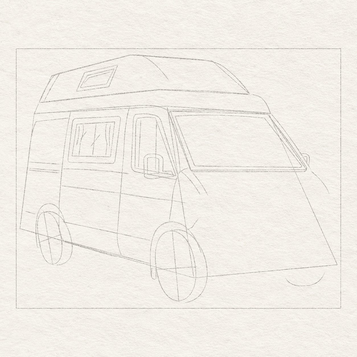
    1. Place the large housing’s upper-left at 7.85 cm across and 6.45 cm down. Within 1.2 cm of width and 1.5 cm of height, shape the housing freehand by eye. From its upper-left, follow the top to a rounded upper-right turn, draw down the right side, round along the bottom and return up the left side to its rounded upper corner. At mid-height its centre is about 1 cm left of the cab glass’s steep front edge.
    2. Inset the glass ⅛–¼ cm, leaving a pale upper rim. From the housing’s lower-right, draw the outer support about 7 mm right and 3 mm down into the cab window’s lower-front frame band, then return to the housing. Inside it, draw a short inner support edge about 5 mm right from the housing. Keep this pencil support light; its inked attachment will reach the painted pillar in Drawing 26A.
    3. The housing covers the lower-front window lines. Leave those hidden guides light; do not ink them through the mirror.
    A smaller narrow mirror housing projects beside the windscreen’s right pillar, with its lower attachment hidden.
    Drawing 11B — Attach the small far mirrorView larger
    Enlarged current far mirror pencil housing, inner glass edge and attachment beside the pillar.
    Detail 11B.1 — Far mirrorEnlarged from this same step. Compare the narrow housing, inner glass edge and attachment beside the pillar. This is the light shape-selection stage.

    Instructions for Drawing 11B — Attach the small far mirror

    1. Place the small housing just outside the right windscreen pillar near its lower quarter, with its top roughly level with the large mirror’s top. Make it half the large housing’s width, excluding the support arm, and just under 1 cm high down to its hidden lower attachment.
    2. Freehand its rounded upper corner and show a narrow glass sliver and outside edge. The pillar hides its lower attachment. Narrow an oversized mirror rather than shrinking the windscreen or adding a floating support.
    Next step — Lay out the interior behind the glass
  2. Step 12 of 38 · Pencil

    Lay out the interior behind the glass

    Inside the windscreen are a rear cabin opening with an open inset return, a bright right pane with three nearby edge strokes, and a low dashboard guide.
    Drawing 12A — the interior behind the glassView larger

    Instructions for Drawing 12A — the interior behind the glass

    1. In the windscreen’s left half, join the rear-opening corners 11 cm across and 4.6 cm down, 13.5 cm across and 4.5 cm down, 13.65 cm across and 6.95 cm down, and 11 cm across and 7 cm down.
    2. Start a short inset ¼ cm right and down from its upper-left. Run 0.85 cm right, rising slightly, then turn down-right to the opening’s lower edge. Leave its left side open.
    3. For the bright right pane, join upper-left 14 cm across and 4.4 cm down, upper-right 15.55 cm across and 4.35 cm down, lower-right 16 cm across and 6.9 cm down, then lower-left 14.2 cm across and 6.9 cm down. Bow its top gently freehand.
    4. About ⅕ cm below the bright pane’s top, draw a short line from ⅛ cm inside its left edge to ⅛ cm before its right edge, rising slightly right.
    5. Start ⅛ cm right and ⅓ cm down from the bright pane’s upper-right corner. Draw down-right to its bottom level, ending about ½ cm right of your starting point.
    6. Start the second stroke ½ cm right and ½ cm down from the first stroke’s start. Draw down-right, ending about ⅔ cm right of this new start and just below the bright pane’s bottom. Keep both strokes inside the windscreen.
    7. Draw the low dashboard from the rear opening’s lower-left toward the right, almost level and slightly above the lower windscreen edge. Stop 0.7 cm before the windscreen’s lower-right inner corner.
    8. Keep the right pane broad and pale. Stop interior lines at the dashboard so they do not enter the bonnet.
    Next step — Place the seats and inside mirror
  3. Step 13 of 38 · Pencil

    Place the seats and inside mirror

    A large headrest and seat back, a smaller partly hidden seat view, and a side-pane seat are placed behind the glazing.
    Drawing 13A — Place the visible seat shapesView larger

    Instructions for Drawing 13A — Place the visible seat shapes
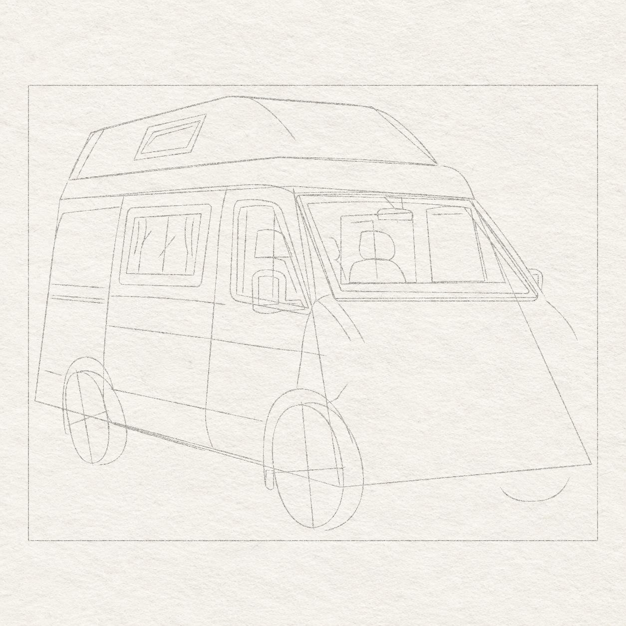
    1. Mark the large headrest’s upper-left at 11.7 cm across and 5.15 cm down. Allow about 1¼ cm of width and 1 cm of height, leaving about ½ cm above it in the rear opening. Shape it freehand by eye: follow a fairly flat top, round down each side and join the sides with a shallow rounded bottom.
    2. Then freehand the seat back from its lower corners down to the dashboard, widening about ⅓ cm on each side.
    3. To its left, place the partly hidden headrest at 10.45 cm across and 5.4 cm down, within about ½ cm of width and ¾ cm of height. Shape its visible contour freehand by eye: round across its top and down the exposed side, stopping where the opening hides it. Show only the visible back down to the dash.
    4. Mark the cab headrest’s upper-left at about 8 cm across and 5.1 cm down. Within 1.3 cm of width and 1 cm of height, shape the headrest freehand by eye: draw across its gently rounded top, round down both sides and join them with a shallow bottom curve.
    5. From the cab headrest’s lower corners, freehand the widening seat back downward. Stop the visible right-hand edge near 9½ cm across and 7⅓ cm down, just above the already drawn mirror support arm. Leave the lower seat hidden behind the mirror housing.
    A shallow rear-view mirror, wider tapered upper attachment and tiny lower tab are placed above and right of the large headrest.
    Drawing 13B — Place the inside rear-view mirrorView larger
    Pencil rear-view mirror above and to the right of the large headrest, with a tapered upper attachment and short lower tab. The steering arcs and wipers have not been drawn yet.
    Detail 13B.1 — Windscreen interiorEnlarged from this same step. Compare the tapered attachment above the shallow rear-view housing and its tiny lower tab. The surrounding interior guides stay light.

    Instructions for Drawing 13B — Place the inside rear-view mirror

    1. Place the inside mirror’s centre 0.6 cm right of the large headrest centre, with its top ¼ cm below the inner upper windscreen edge. Within 1.25 cm of width and 0.4 cm of height, shape a shallow housing freehand by eye: curve along its nearly flat top, round the right end, return along the bottom and round the left end to close it, then add its short lower tab by eye, stopping about ⅓ cm above the headrest.
    2. Connect it to the upper seal with a tapered attachment, 0.6 cm wide at the seal, tapering to ¼ cm wide just above the housing.
    3. Leave about ⅓ cm between the lower tab and headrest; do not carry the attachment through the seat. If centred over the headrest by mistake, move only the mirror and attachment to their right-hand offset.
    Next step — Place the steering arcs and low wipers
  4. Step 14 of 38 · Pencil

    Place the steering arcs and low wipers

    Two shallow steering-wheel arcs rise above the dashboard level, with their right tips stopping slightly above the straight placement line.
    Drawing 14A — the visible steering-wheel arcsView larger
    Two separate pencil steering arcs above the dashboard guide, with the rear-view mirror and seats retained. Wiper paths have not been drawn yet.
    Detail 14A.1 — Windscreen interiorEnlarged from this same step. The two visible steering arcs sit in front of the selected interior guides; compare their separate ends and the gap above the dashboard level.

    Instructions for Drawing 14A — the visible steering-wheel arcs
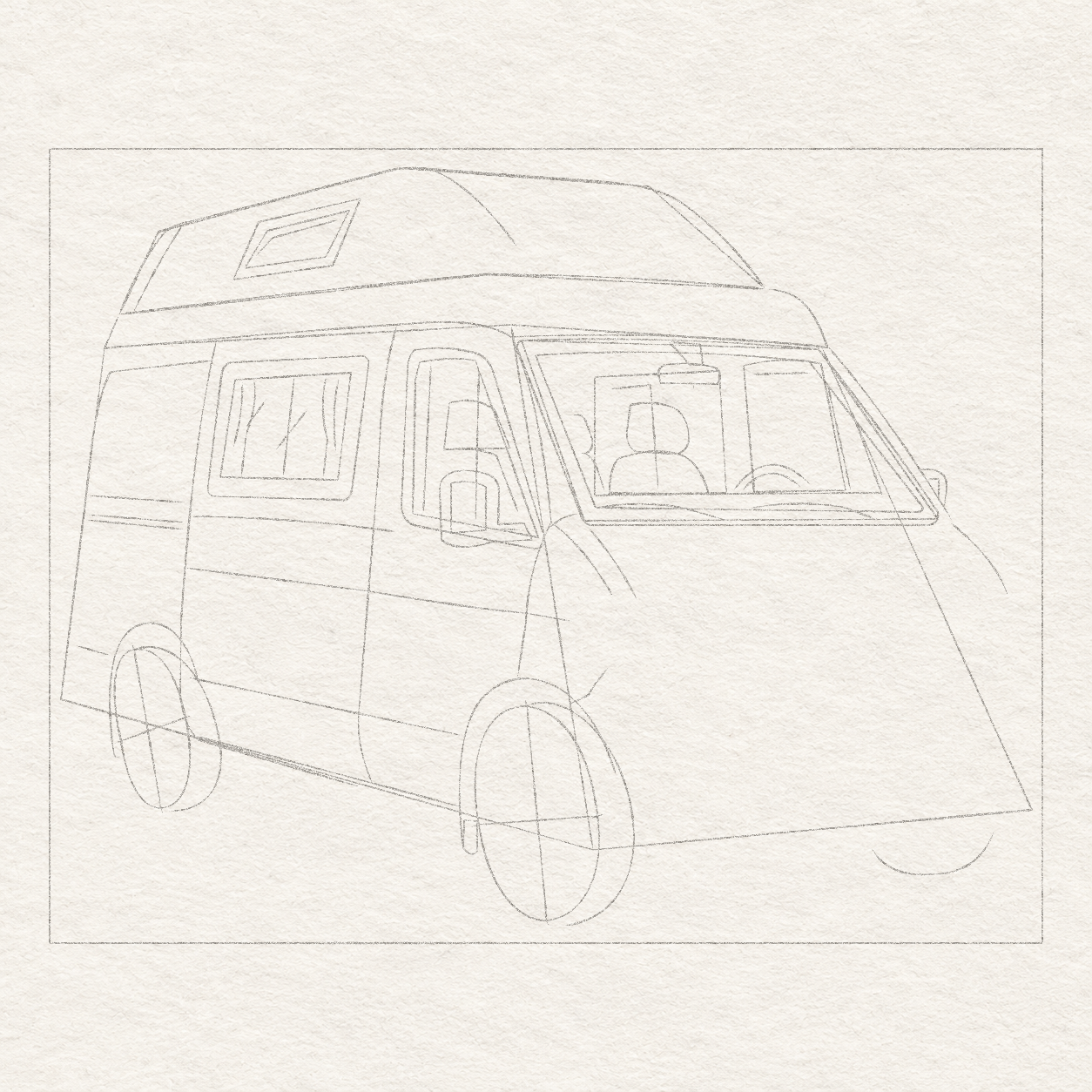
    1. Rehearse, then freehand a shallow outer arc from just left of the bright pane’s lower-left corner to about 1.6 cm right, near its lower middle. Raise its high point ½ cm above the dashboard, slightly right of the arc’s middle.
    2. Freehand an inner arc ⅛–¼ cm away. Keep left ends close to the straight dash guide and right ends about ⅛ cm above it. The later inked dashboard curves up behind that right-hand gap; do not extend the arcs to the guide or complete a hidden lower oval.
    Two low curved wiper paths follow the glass bottom; their short down-right returns end within the lower seal band.
    Drawing 14B — two low wiper bladesView larger
    Two low pencil wiper paths with short angled returns inside the lower windscreen seal; the seats, mirror and steering arcs remain visible.
    Detail 14B.1 — Windscreen interiorEnlarged from this same step. Distinguish the slim blade paths from the seal edges. The short blade returns enter the lower seal band but stop above its outer bottom edge.

    Instructions for Drawing 14B — two low wiper blades

    1. Keep both blades low in the glass, with their short returns entering the bottom seal and stopping above its outside edge. From inside the windscreen’s lower-left corner, freehand the left blade 1.8 cm right, almost level, then turn down-right for 0.9 cm within those limits.
    2. Start the right blade ½ cm right and ¼ cm above that return’s end. Freehand a curve 1.9 cm right, with a shorter down-right return ending inside the same seal band, above its outside edge.
    3. Keep both paths thin, light and tapered. Neither blade crosses a seat or steering arc; shorten a return reaching the bonnet.
    Next step — Shape the headlamps and reflector pockets

Chapter 4 — Draw the lights, wheel centres and fittings

8 steps · 11 progress drawings · Pencil
  1. Step 15 of 38 · Pencil

    Shape the headlamps and reflector pockets

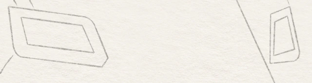
    A wide near headlamp and a narrower tall far headlamp are framed below the two bonnet-turn endpoints, each with an inset lens.
    Drawing 15A — Place the two headlampsView larger
    Enlarged current near and far headlamp areas, preserving their exact frames and any reflector divisions introduced so far.
    Detail 15A.1 — Near and far headlampsEnlarged from this same step. Compare the wider near lamp with the compressed far lamp; the frames, inner divisions and pale lower strip are separate decisions in the stages that introduce them.

    Instructions for Drawing 15A — Place the two headlamps
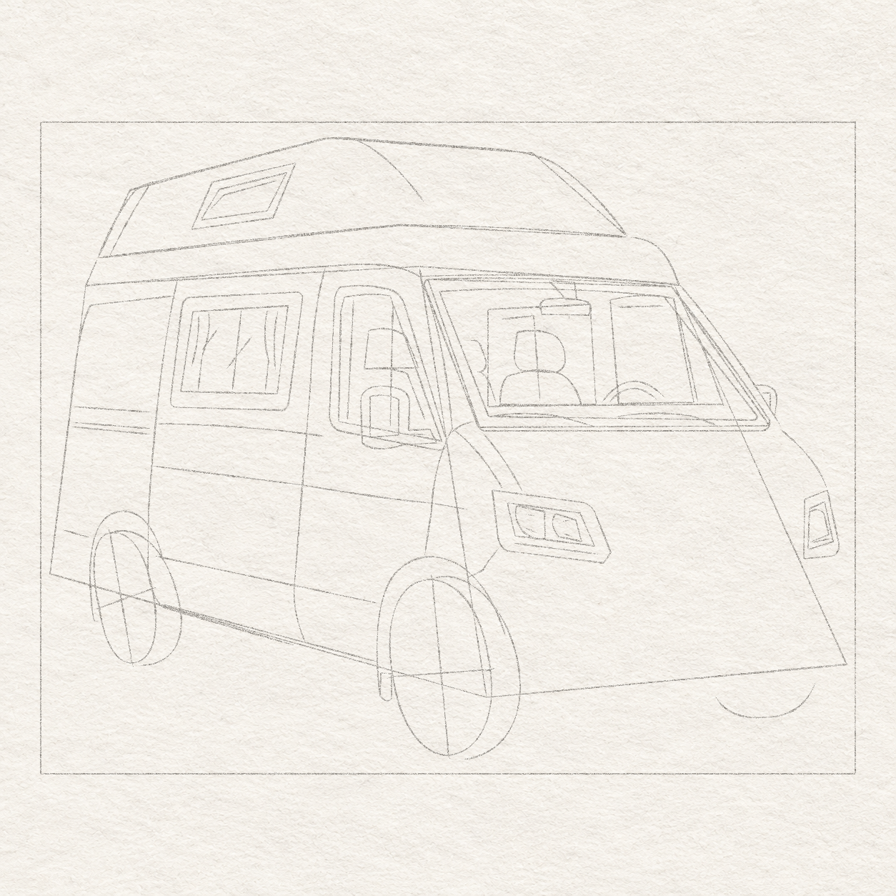
    1. Lightly mark the near lamp’s upper-left dot at 11.1 cm across and 9 cm down.
    2. Mark the top bends near 13¼ cm across and 9⅓ cm down and 13⅔ cm across and 9⅔ cm down. From the upper-left dot, draw the top edge through those bends.
    3. Mark the lower-left corner at 11.45 cm across and 10.55 cm down and lower-right at 13.8 cm across and 10.8 cm down. Join these two dots for the sloping bottom edge. Connect each side to the top, rounding the corners freehand. The two bonnet curves meet the lamp’s top edge.
    4. Inside the wide lamp, draw a smaller sloping four-sided lens. Leave about ¼–⅓ cm of frame above and on both sides, and a wider ⅓–½ cm pale strip below. The opening is about 2 cm wide and ¾ cm deep between its top and bottom edges at the middle.
    5. Use the far bonnet curve’s lower endpoint as the narrow lamp’s upper-right corner. Mark the other three corners at 18.75 cm across and 9.25 cm down, 18.75 cm across and 10.7 cm down and 19.45 cm across and 10.65 cm down, then join them freehand, keeping the left side upright and bowing the right.
    6. Inside the far lamp, draw a smaller slanted lens outline about ⅛ cm in from both side edges and ¼ cm from its top and bottom. Keep the narrow outer frame and lower strip clear.
    7. Leave a wide grille gap between lamps. Their apparent widths differ; use these corners rather than an undrawn body edge.
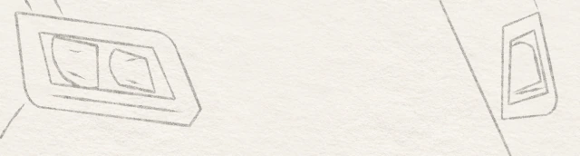
    Unequal reflector pockets, small facets and pale lower strips are selected inside the near and compressed far headlamp lenses.
    Drawing 15B — the reflector divisionsView larger
    Enlarged current near and far headlamp areas, preserving their exact frames and any reflector divisions introduced so far.
    Detail 15B.1 — Near and far headlampsEnlarged from this same step. Compare the wider near lamp with the compressed far lamp; the frames, inner divisions and pale lower strip are separate decisions in the stages that introduce them.

    Instructions for Drawing 15B — the reflector divisions

    1. Inside the wide lens, freehand two unequal reflector pockets: a deeper rounded left one slightly under half the lens width, and a right one just over a third, straighter outside and curved inside. Leave about ⅛ cm between them.
    2. Inside each near-lamp pocket, add one short stroke near the top and another near the bottom, leaving pale paper between them. Keep these small accents inside their pocket; their spacing may vary.
    3. Draw the thin division just above the near lamp’s pale lower strip. Inside the far lens, freehand one narrow curved reflector shape, leaving a gap from the lens border and its lower strip.
    Next step — Build the grille around its badge
  2. Step 16 of 38 · Pencil

    Build the grille around its badge

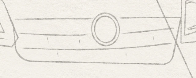
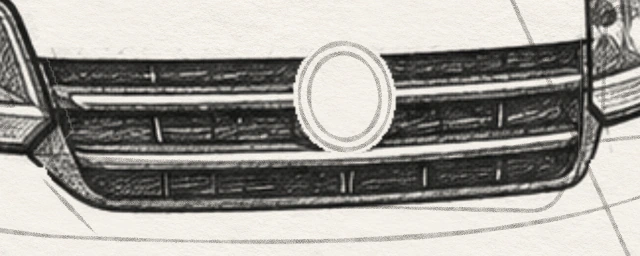
    The grille perimeter and two light channels surround a badge reserve; short pencil marks locate pale divider breaks inside the future dark rows.
    Drawing 16A — the grille around its badgeView larger
    Enlarged current upper grille and badge area, showing the actual channel spacing, retained guides and present reserves.
    Detail 16A.1 — Upper grille and badgeEnlarged from this same pencil step. Locate the blank badge oval first, then the grille channels and divider locations. Only the channel that meets the oval is interrupted; keep the lower channel continuous.

    Instructions for Drawing 16A — the grille around its badge

    1. Mark the badge centre at 16.55 cm across and 10.3 cm down, about ¼ cm right of the lamp-gap midpoint. Allow an almost upright oval 0.8 cm wide and 0.95 cm high around that centre. Shape it freehand by eye: curve over the top, around the right side and bottom, then return up the left side. Follow that oval with a smaller loop inside it, leaving its pale rim open.
    2. Around the badge, allow a grille about 4.8 cm wide and 1.3 cm high. Shape the perimeter freehand by eye: follow the gently sloping top on either side of the badge, round both ends and return along the shallow lower edge. Its upper edge sits about ⅓ cm above the badge centre and stops behind the oval.
    3. From the grille’s top edge, measure about ½ cm down for the upper light channel and 0.9 cm down for the lower one. Keep the upper channel broken behind the badge and the lower continuous below it. Freehand each as a narrow gently curved pale band, about ⅛–¼ cm high.
    4. Check that the upper channel stops at the badge and the lower remains continuous below it.
    5. Inside the dark rows, mark short nearly vertical breaks to leave pale during filling. Their spacing may vary; they are not black bars across the light channels.
    6. Keep the badge rim, row gaps and both lamp lenses separate. Widen a closing light channel before ink.
    Next step — Place the lower light pockets
  3. Step 17 of 38 · Pencil

    Place the lower light pockets

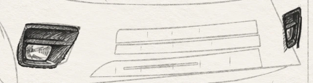
    Two unequal lower fog-light pockets and their small inset lenses are located below the lamps, leaving the painted space between them open.
    Drawing 17A — Place the two lower fog-light pocketsView larger
    Enlarged current near and far lower fog-light pockets and their differently compressed shapes.
    Detail 17A.1 — Lower fog-light pocketsEnlarged from this same step. The near pocket is wider; the far pocket is narrow. Keep each pale lens distinct from its surrounding recess when the ink stage introduces the dark areas.

    Instructions for Drawing 17A — Place the two lower fog-light pockets

    1. Place the wide near fog pocket’s upper-left at 12 cm across and 12.15 cm down. Within about 1.8 cm of width and 1.15 cm of height, shape the pocket freehand by eye: draw its top edge, round down the right side, follow the lower edge and return up the left side, rounding each turn.
    2. In the near pocket’s lower-left, shape a slanted lens freehand by eye within about 0.85 cm of width and 0.4 cm of height: curve along its lower sloping edge, turn at its right end and return along its upper edge to close it. Leave about ⅕ cm to the pocket’s left and bottom edges, with more dark space above and to the right.
    3. Mark the far-pocket corners at 19.35 cm across and 11.9 cm down, 19.7 cm across and 11.7 cm down, 19.8 cm across and 12.5 cm down and 19.4 cm across and 12.85 cm down, then join them in order. In its lower half, draw a narrow slanted lens, following the pocket’s side slopes and leaving a small gap on every side.
    4. Compare each pocket with its lamp above. Keep the near one much wider and leave painted space between them for the intake slots.
    5. Use the box and existing lamps, not an undrawn bumper corner. If a pocket is misplaced, fix its corners before its lens.
    Next step — Select the three intake slots and reserves
  4. Step 18 of 38 · Pencil

    Select the three intake slots and reserves

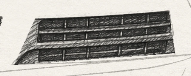
    Three separately closed lower intake slots have two painted gaps between them; the bottom row has a flared left cap, divider location marks and a narrow bright reserve.
    Drawing 18A — Select three separate lower intake slotsView larger
    Enlarged three lower intake rows with the lower-left cap, separate painted gaps, divider locations and bottom interior bright reserve.
    Detail 18A.1 — Three lower intake rowsEnlarged from this same step. Keep the two painted gaps between the three rows distinct from the small divider breaks and the narrow bright reserve inside the bottom row.

    Instructions for Drawing 18A — Select three separate lower intake slots

    1. Freehand the upper closed slot through corners 14.7 cm across and 12.3 cm down, 18.5 cm across and 12.05 cm down, 18.6 cm across and 12.4 cm down, and 14.55 cm across and 12.7 cm down. Bow its long edges gently.
    2. Freehand the middle closed slot through 14.6 cm across and 12.75 cm down, 18.6 cm across and 12.5 cm down, 18.65 cm across and 12.8 cm down, and 14.5 cm across and 13 cm down.
    3. Start the bottom row at 14.6 cm across and 13.2 cm down, rise right to 18.6 cm across and 12.85 cm down, turn down to 18.7 cm across and 13.4 cm down, then freehand the curve back to 13.8 cm across and 13.65 cm down. Round its flared left cap back to the start.
    4. Keep three separate closed rows, with two painted gaps at least a pen-width wide at your drawing size. The bottom row extends farther left and lower.
    5. Mark the short nearly vertical pale divider breaks inside the rows. Their spacing may vary; never draw them as black lines across a painted gap.
    6. Inside the bottom row, reserve a thin bright strip with two close parallel pencil lines from 14.8 cm across and 13.4 cm down to 16.9 cm across and 13.25 cm down. For later shading, use the upper row’s left end, the middle row’s left end and the bottom row’s far-left tip to locate the separate triangular area beside the rows.
    Next step — Choose the bumper curves and tyre overlap
  5. Step 19 of 38 · Pencil

    Choose the bumper curves and tyre overlap

    Selected bumper curves include its upper turn, bowed lower edge, fine left grille return and a painted-body overlap boundary in front of the near tyre.
    Drawing 19A — Choose the bumper curvesView larger
    Enlarged current pencil outside-left grille return, adjacent grille outline, pale gap and join to the upper bumper-turn guide.
    Detail 19A.1 — Fine return beside the grilleEnlarged from this same pencil step. Follow the separate light curve down-right from beside the lower-left grille bevel to the upper bumper turn. Keep its pale gap from the grille outline; use the full view above for placement.

    Instructions for Drawing 19A — Choose the bumper curves

    1. Start just below the near lamp’s lower-left outside corner. Freehand a curve down-right beneath the whole near lamp. Below the grille, leave about ¼ cm between this curve and the grille’s bottom outside edge at half its width. Then rise beneath the far lamp.
    2. For the lower bumper edge, start just right of the large tyre, nearly level with the straight front guide’s near corner.
    3. Freehand this lower curve, bowing it ¼ cm below the straight guide at its middle. Rise to the far corner, ending ½ cm below the far fog pocket.
    4. Keep about ½ cm of painted bumper below the bottom intake slot. Round the far turn rather than making a sharp box corner.
    5. Outside the grille’s lower-left slanted corner, start a separate fine curve ⅛ cm out and below it. Freehand a sweep down-right about ½ cm to meet the upper bumper line.
    6. Leave a pale gap between this fine curve and the thick grille border. If it closes, erase only the fine curve and move it slightly outward.
    7. From the existing arch-to-lamp bend at 10.85 cm across and 11 cm down, freehand the body’s left overlap through 11 cm across and 12 cm down and 11.25 cm across and 13.65 cm down, rounding into the bumper near 11.75 cm across and 14 cm down.
    8. The painted body stays above/right of that overlap, covering part of the tyre’s right depth guide. Keep only the exposed rubber below/left for ink; do not treat the new curve as another tyre edge.
    Next step — Draw the near rim, openings and bolts
  6. Step 20 of 38 · Pencil

    Draw the near rim, openings and bolts

    Three nested tilted ovals locate the larger wheel’s rim, pale lip and small hub within the tyre face.
    Drawing 20A — the near rim and hubView larger
    Enlarged near wheel from the current stage, including the rim, surrounding tyre and adjacent body overlap.
    Detail 20A.1 — Near wheel and body overlapEnlarged from this same step. Distinguish the rim and hub from the surrounding tyre and the separate body edge; the full view above preserves their placement.

    Instructions for Drawing 20A — the near rim and hub
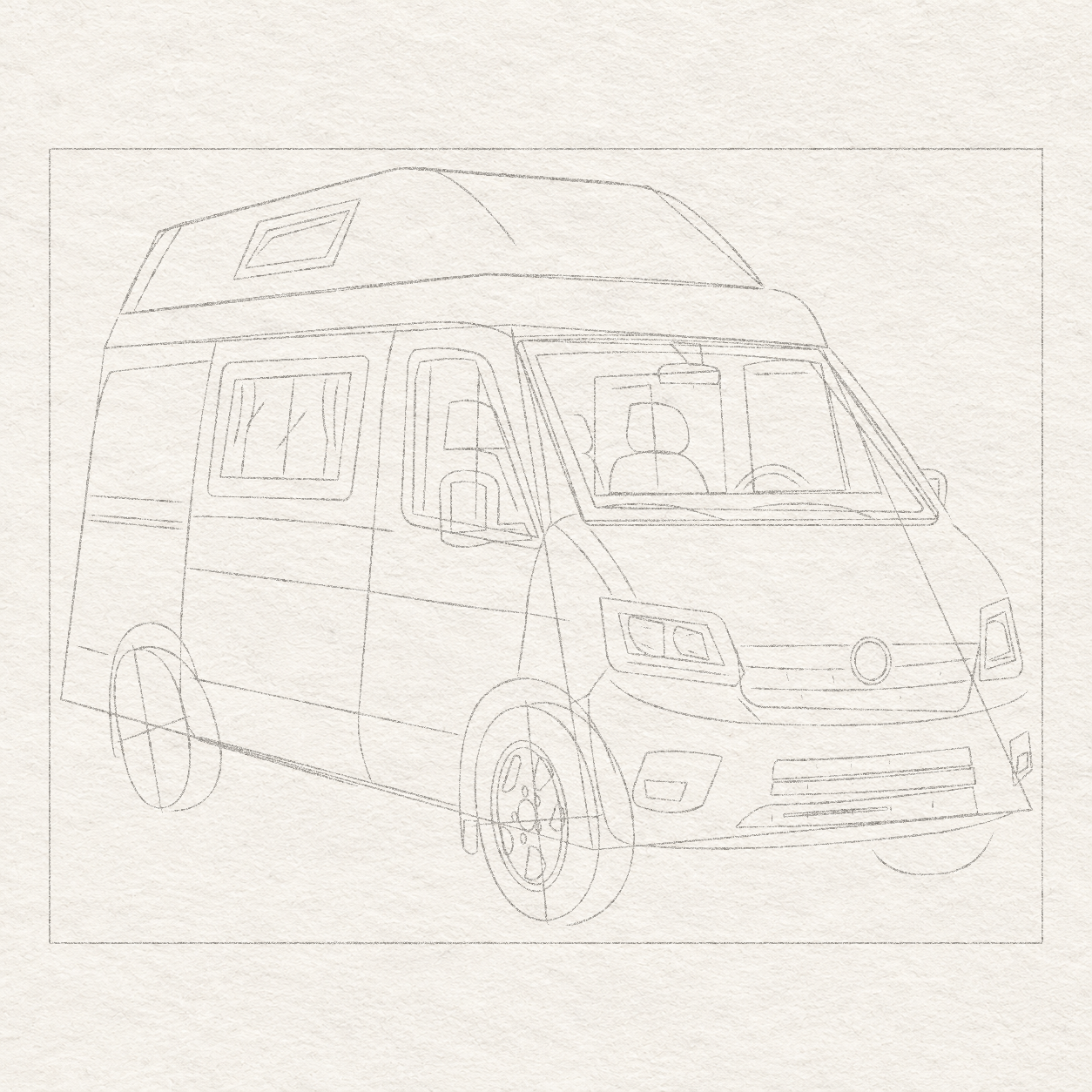
    1. Lightly mark the large rim’s top and bottom inside the tyre: top ¾ cm below tyre top, bottom a little over ½ cm above tyre bottom. Mark left and right points for a width about 1½ cm and height about 3 cm, with the same lean as the tyre and tread space on the right.
    2. Rehearse, then freehand one oval through those four dots. Draw a smaller oval ⅛ cm inside it for the metal lip. At the rim’s centre, allow a separate hub oval about ⅓ cm wide and ⅔ cm high with the same lean. Shape it freehand by eye: curve from its top around the right side and bottom, then return up the left side to close it.
    3. Keep rubber visible all around. Narrow a circular-looking rim rather than closing its sidewall gap.
    Five unequal rounded openings and five smaller bolt marks are arranged around the near hub, leaving metal bridges between them.
    Drawing 20B — the near rim openings and boltsView larger
    Enlarged near wheel from the current stage, including the rim, surrounding tyre and adjacent body overlap.
    Detail 20B.1 — Near wheel and body overlapEnlarged from this same step. Separate the five larger rim openings, the small bolt marks and the pale bridges; keep the hub and outer lip distinct from them.

    Instructions for Drawing 20B — the near rim openings and bolts

    1. Between hub and inner rim, freehand five rounded openings by eye: two above, one right, one below and one lower-left. Stretch the upper pair with the tall rim; keep the side openings shorter, not five equal circles. Shape each loop by eye between hub and rim: curve down one side, round its lower end and return up the other side, rounding back to the start.
    2. Leave pale metal bridges between the openings, linking hub to rim. Narrow any hole touching the hub or rim. By eye, draw five separate tiny freehand loops close around the hub, curving around each oval and back to its start; spacing may vary while the metal bridges stay open.
    Next step — Draw the smaller rear rim and openings
  7. Step 21 of 38 · Pencil

    Draw the smaller rear rim and openings

    A narrower tilted rim, fine inset lip and small central hub are placed inside the rear tyre face.
    Drawing 21A — the rear rim and hubView larger
    Enlarged rear wheel from the current stage, showing the exact retained guides and current rim or tyre marks.
    Detail 21A.1 — Rear wheelEnlarged from this same step. Compare the rim, hub and outer tyre as separate nested forms; use the full view above for their position on the van.

    Instructions for Drawing 21A — the rear rim and hub
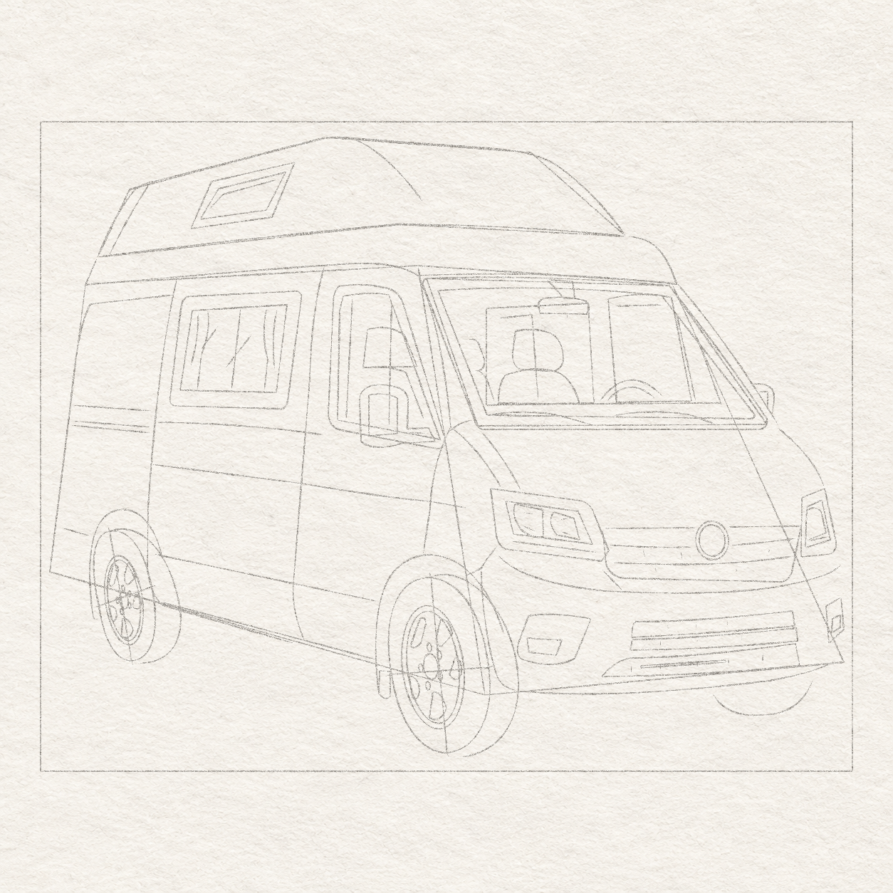
    1. Inside the small tyre, allow a tilted rim oval about 0.9 cm wide and 2.2 cm high, leaving about ½ cm of rubber above and below and tread space to its right. Follow the tyre’s lean by eye: curve freehand over the rim’s top, down its right side, around the bottom and back up the left side.
    2. Freehand a second oval about 0.1 cm inside the rim for the pale metal lip. At their centre, allow a separate hub oval about 0.2 cm wide and 0.4 cm high. Shape the tiny loop freehand by eye, curving down one side, rounding its bottom and returning up the other side to close it. Keep rubber outside the rim and room for openings around the hub.
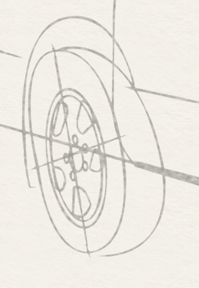
    Five larger openings and small bolt marks are fitted to the rear rim’s narrow oval while reserving pale metal bridges.
    Drawing 21B — the rear rim openingsView larger
    Enlarged rear wheel from the current stage, showing the exact retained guides and current rim or tyre marks.
    Detail 21B.1 — Rear wheelEnlarged from this same step. Separate the five larger rim openings, the tiny bolt marks and the pale bridges. The retained axes locate the centre; they are not extra slots to ink.

    Instructions for Drawing 21B — the rear rim openings

    1. Freehand five unequal rounded openings by eye around the small hub: two above, one right, one below, one lower-left. Shape each closed loop by eye between hub and rim: curve around one side and its rounded end, then return around the other side. Keep metal bridges to hub and rim; do not copy the larger wheel’s opening widths.
    2. Add separate tiny bolts near the hub; dots are fine at this scale. If the rim becomes one dark patch, reduce the openings and widen the metal bridges, keeping the checked tyre and rim outlines fixed.
    Next step — Place the handles, hatch and rear light
  8. Step 22 of 38 · Pencil

    Place the handles, hatch and rear light

    The current pencil fittings include a tall sliding handle, short horizontal cab bar crossing upper and lower rounded backing ends, rear filler hatch, narrow light and small lower return.
    Drawing 22A — Add handles, filler hatch and rear lightView larger
    Enlarged pencil filler hatch, short latch, narrow rear light and lower bumper return from the current stage.
    Detail 22A.1 — Rear fittingsEnlarged from this same step. These are light placements for the filler hatch, its short latch, rear light and small bumper return; keep them separate from the rear panel outline.
    Enlarged current light tall sliding-door handle, short cab-door handle and rounded backing with their exact placement guides.
    Detail 22A.2 — Door handles and backingEnlarged from this same step. The tall sliding handle is separate from the horizontal cab bar. The cab bar hides the middle of its narrow upright backing; show the rounded backing ends above and below it.

    Instructions for Drawing 22A — Add handles, filler hatch and rear light

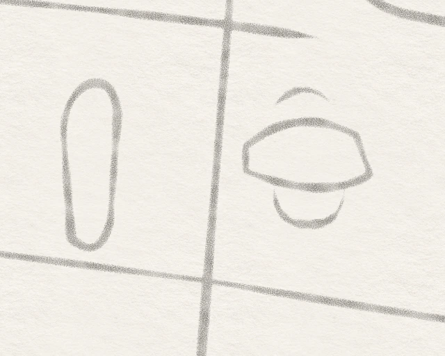
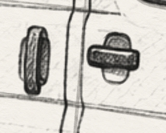
    1. Below the large side window, freehand the tall handle as a narrow upright shape with rounded ends just left of the sliding door’s front seam—the seam between the large window and cab window. Start 1 cm below the window and allow the handle ¾ cm of height and ¼ cm of width. Shape it freehand by eye: curve down one side, round the lower end, return up the other side and round its top to close it.
    2. Place the short cab handle just right of that seam, near the tall handle’s middle: about ⅔ cm wide and ¼ cm high. Shape that short bar freehand by eye, following its upper edge, rounding its right end and returning along its lower edge around the left end.
    3. For the backing behind the short bar, use a centred upright shape about 0.4 cm wide and ⅔ cm high. Freehand only its rounded end above the bar; leave the lower end for the next action.
    4. Freehand the backing’s lower return from one bar join down around its shallow base to the other. Do not draw through the bar or omit the lower end.
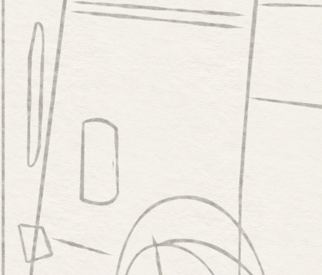
    5. Freehand the filler hatch as a small rounded rectangle above-left of the rear arch, leaving a clear gap from the arch. Keep it ½ cm wide and 0.9 cm high, with its lower edge ½ cm above the tyre top. Shape it by eye: follow its top, round down the right side, return along the bottom and round back up the left side. Add its short latch on the right.
    6. At the van’s far-left rear edge, start the thin light level with the two short strip lines beneath the blank rear panel. Freehand its narrow sliver 1.6 cm down. Below it, draw the small angled bumper end around the existing short rear bumper line, joining it back into the rear body edge.
    7. Keep fittings separate from panel seams. Move or narrow a fitting that accidentally touches a seam.
    Next step — Ink the raised roof, window and band

Chapter 5 — Ink the roof, windows and interior

6 steps · 14 progress drawings · Fineliner
  1. Step 23 of 38 · Fineliner

    Ink the raised roof, window and band

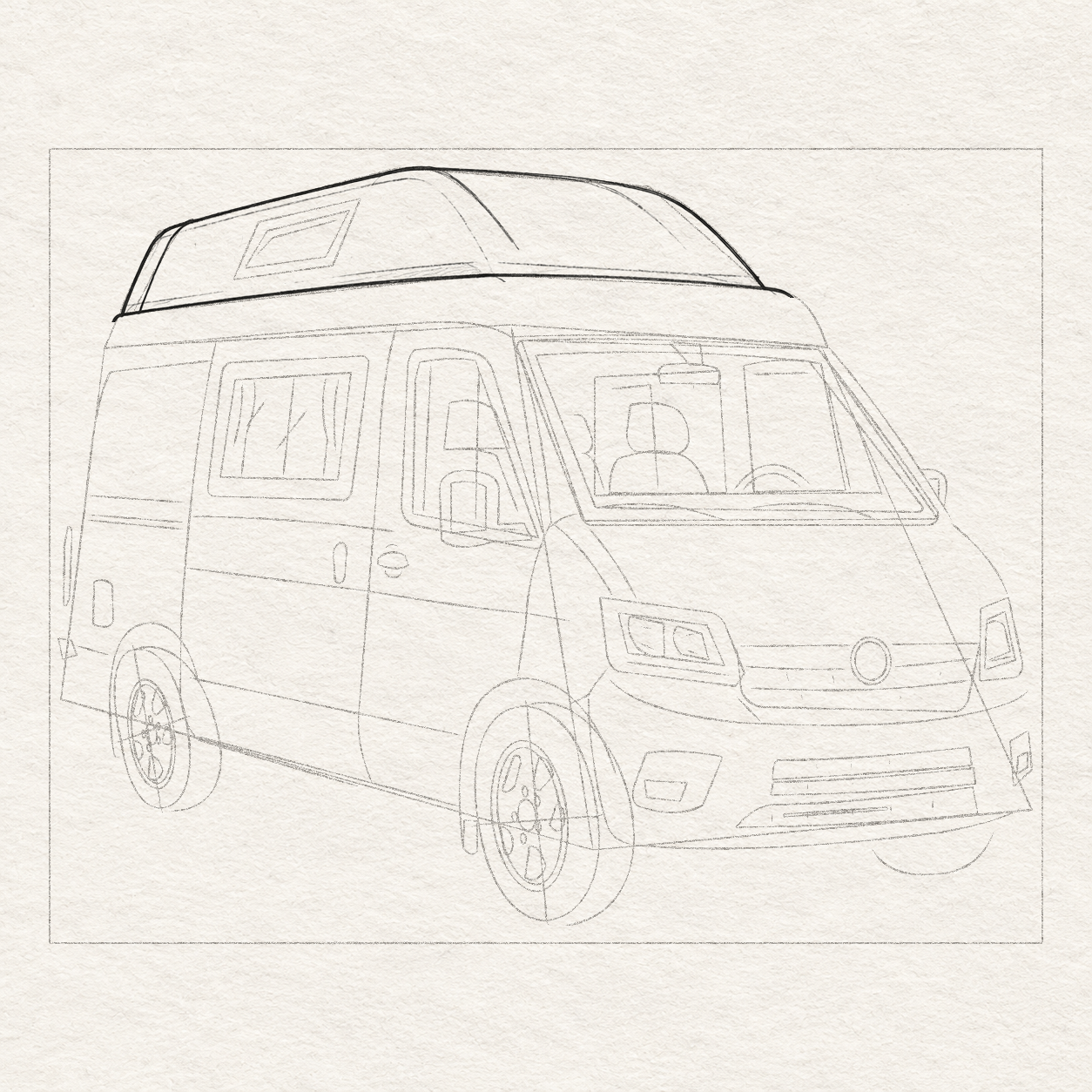
    The raised roof’s rounded contour, lower edge, rear inset and cap-turn accent are inked while its broad surface stays light.
    Drawing 23A — the raised roof contoursView larger

    Instructions for Drawing 23A — the raised roof contours
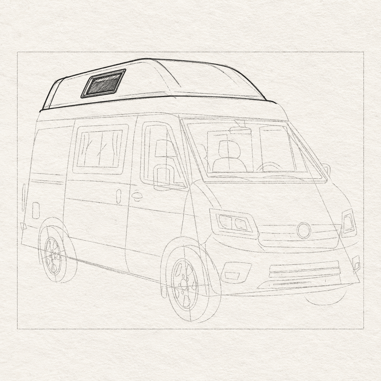
    1. Test the pen on scrap, keeping all pencil until the ink dries. Ink the selected rounded shoulder, broad top and front cap to its fixed base, not the angular guide. Stop at a doubled black edge: permanent ink cannot be erased like pencil.
    2. Ink the lower roof edge, rear inset and short cap curve. Leave the small window for Drawing 23B; keep the broad roof mostly white, with only sparse light surface strokes.
    The small roof window has a dark slanted frame, a narrow pale lip, diagonal pane hatching and an uncovered bright slash.
    Drawing 23B — the little roof windowView larger
    Enlarged current inked roof-window frame and glazing with the preserved upper-left bright slash.
    Detail 23B.1 — Roof windowEnlarged from this same step. Keep the thin light frame edges and the upper-left bright glazing slash separate from the surrounding ink tone.

    Instructions for Drawing 23B — the little roof window
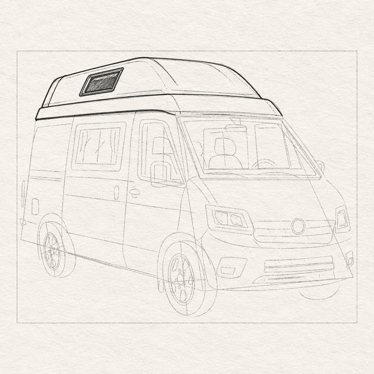
    1. Ink the slanted window’s outside and inside frames, leaving the pale lip open. Darken only the frame band with close short strokes.
    2. Shade down-left inside the pane, preserving its upper-left bright slash. Keep the window’s slant and stop darkening before the pale rim disappears.
    The broad band above the glazing is outlined in ink with a rounded front turn and sparse lower-edge strokes.
    Drawing 23C — the band above the cabView larger

    Instructions for Drawing 23C — the band above the cab

    1. Keep the already inked lower roof edge as the band’s upper boundary. Ink the selected lower band curve and rounded front return, wider over the long side and narrower at the front. Add the short turn above the windscreen.
    2. Keep the lower edge above both cab panes, never across the windscreen opening. Add only a few strokes near that edge; the band stays lighter than the glass frames.
    Next step — Ink the side window and curtains
  2. Step 24 of 38 · Fineliner

    Ink the side window and curtains

    The side window’s outer seal, inset lip and central divider are inked as continuous frame bands around two open panes.
    Drawing 24A — the side-window frame bandsView larger

    Instructions for Drawing 24A — the side-window frame bands
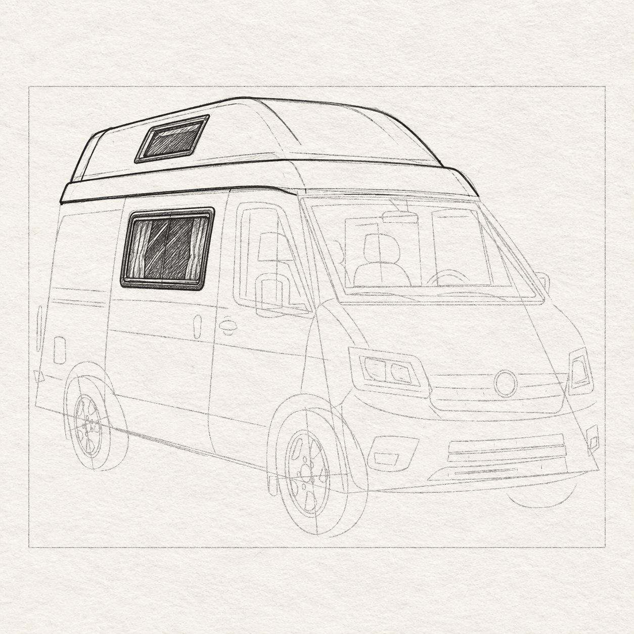
    1. Ink the side window’s rounded outside, inset pane edges and sloping divider. Darken the frame bands while keeping the pale inset lip open.
    2. Stop the divider at the inner sill. Leave panes and separate curtain areas blank for Drawing 24B, rounding corners rather than tracing the hard guide box.
    Lighter curtain shapes and bright gaps interrupt diagonal hatching inside the darkened side-window panes.
    Drawing 24B — the curtains and glass toneView larger

    Instructions for Drawing 24B — the curtains and glass tone

    1. Ink each wavy curtain edge and its short fold inside its pane. Add a few nearly vertical folds between the curtain and outside frame.
    2. Shade the clear glass down-left between the curtains, stopping at the frame and divider. Leave narrow white stripes around the two short diagonal pencil marks; do not ink those marks as black lines. Keep the curtains lighter.
    Next step — Ink the cab window and visible seat
  3. Step 25 of 38 · Fineliner

    Ink the cab window and visible seat

    The raked cab-window seal and pale lip are inked; its two internal upright divisions remain light pencil for the next stage.
    Drawing 25A — the cab-window frameView larger

    Instructions for Drawing 25A — the cab-window frame
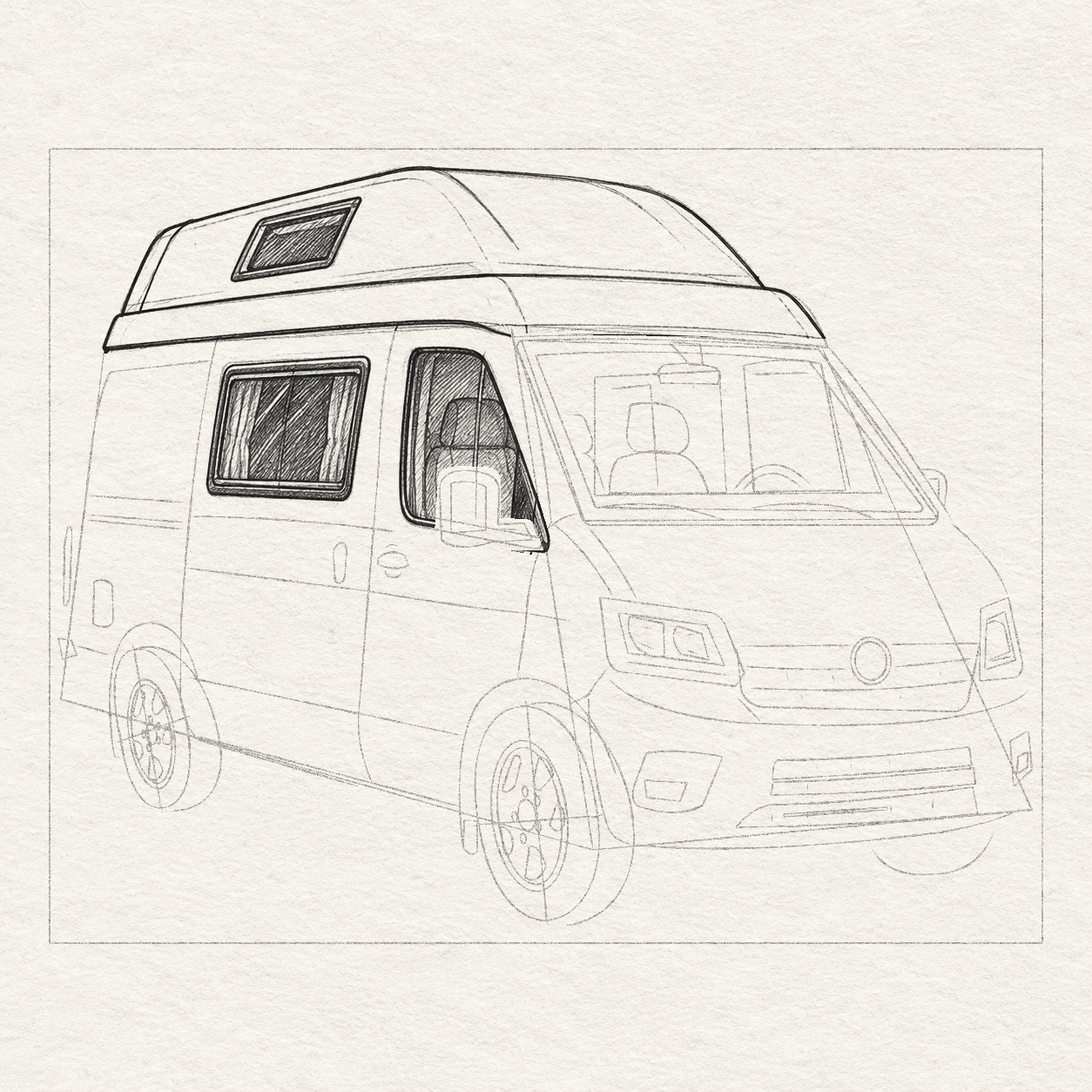
    1. Ink the rounded upper rear corner, steep front edge and inner frame of the cab window. Darken the seal with short strokes, retaining a narrow pale lip and leaving the pane unfilled.
    2. Stop the lower-front frame behind the mirror reserve. Leave both internal divisions in pencil for Drawing 25B; do not ink through the housing.
    The front glazing upright remains visible with a narrow pale strip across the inked seat view, while the lower mirror reserve interrupts the upright and seat.
    Drawing 25B — the seat visible through the side paneView larger

    Instructions for Drawing 25B — the seat visible through the side pane

    1. At the front internal division, reserve a narrow pale strip and ink its fine sides, stopping its lower part at the mirror. Ink the separate rear division; both stop at the inner window frame.
    2. Ink the rounded headrest and widening seat back, stopping at the pale front strip instead of crossing it. Let the mirror hide the seat’s lower-front part.
    3. Shade seat and glass with short diagonals around that strip, frame lip and bright gaps. Preserve rounded seat corners before darkening.
    Next step — Ink the three mirrors and their attachments
  4. Step 26 of 38 · Fineliner

    Ink the three mirrors and their attachments

    The near mirror’s rounded housing, pale upper rim, darker inset glass and short support arm are inked over the cab pane.
    Drawing 26A — the near mirror and its armView larger

    Instructions for Drawing 26A — the near mirror and its arm
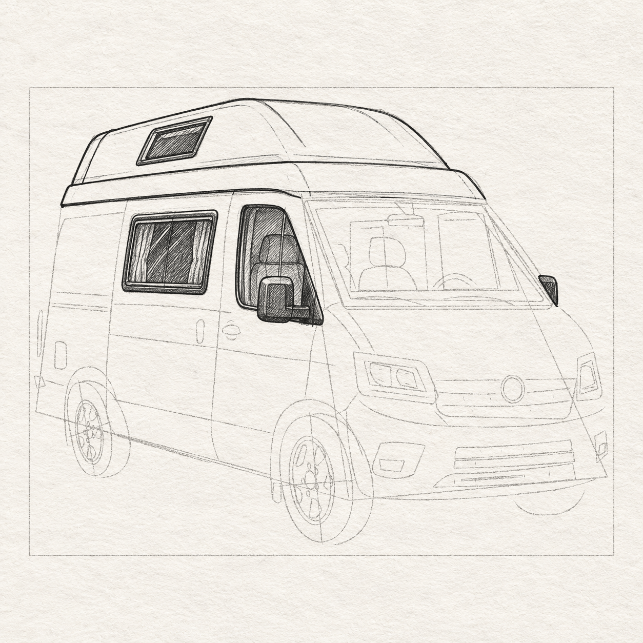
    1. Ink the large rounded housing and inset glass. Keep its pale upper rim; shade diagonally inside the glass, leaving a small lighter edge.
    2. Ink and extend the support from the housing’s lower-right to the painted pillar between the cab window and windscreen, about 1 cm right in total and slightly down. Ink the housing’s dark underside so this connection is visible. Stop old window lines behind it; the thin upright above belongs to the window, not a new aerial.
    The narrow far mirror has an inked rounded edge, dark glass and a thin pale upper rim beside the painted pillar.
    Drawing 26B — the narrow far mirrorView larger
    Enlarged current inked far mirror with pale inner glass and its short pillar attachment.
    Detail 26B.1 — Far mirrorEnlarged from this same step. Keep the slim pale glass distinct from the inked outer edge and the short attachment to the pillar.

    Instructions for Drawing 26B — the narrow far mirror
    1. Ink the far mirror’s rounded top and narrow outside turn. Darken its glass with a few close strokes, retaining a thin pale upper rim.
    2. Keep the lower attachment hidden by the pillar and the housing small and touching it. Add no complete rectangle or outside support; stop before it becomes a solid blob.
    The rear-view mirror housing, tapered dark upper attachment and little lower tab are inked above the large headrest.
    Drawing 26C — the rear-view mirror and attachmentView larger
    Inked rear-view mirror with a dark tapered attachment and short lower tab above the still-pencil headrest. The steering and wiper guides remain pencil.
    Detail 26C.1 — Windscreen interiorEnlarged from this same step. The rear-view mirror and attachment are now inked; the other interior features remain at their current earlier stage.

    Instructions for Drawing 26C — the rear-view mirror and attachment

    1. Ink the shallow inside-mirror housing with nearly parallel top and bottom. Darken its tapered attachment, 0.6 cm wide at the seal, narrowing to ¼ cm wide just above the housing.
    2. Make the attachment touch both seal and housing; follow the existing pencil tab with ink, keeping the gap above the headrest open. Shade the face lighter than its attachment and preserve its offset right of the headrest centre.
    Next step — Ink the windscreen seal and painted pillar
  5. Step 27 of 38 · Fineliner

    Ink the windscreen seal and painted pillar

    A dark bowed windscreen seal surrounds the glazing, with the right painted-pillar strip left light beside its outside contour.
    Drawing 27A — the windscreen’s outer sealView larger

    Instructions for Drawing 27A — the windscreen’s outer seal

    1. Leave the lower dashboard and wiper strip clear for its later pass. Keep the painted pillar pale outside the glass seal.
    2. Work around the already inked rear-view attachment. Ink the chosen outer glass and seal, with rounded corners and a gently bowed top. Darken the narrow top and side seal bands between those edges with close short strokes. Keep the painted pillar and lower dashboard/wiper strip clear.
    3. Keep the painted pillar pale outside the seal. On the right, ink its separate outside edge and taper the white strip toward the roof.
    4. Stop this pillar edge at the bonnet corner. Do not trace the old body-box diagonal through the bonnet.
    5. Work around the already inked rear-view attachment at the upper seal instead of drawing through it.
    6. Keep the wider glass base framed on every side; stop before adding a doubled black outside edge.
    Next step — Finish the seats, glass and low wipers
  6. Step 28 of 38 · Fineliner

    Finish the seats, glass and low wipers

    The two visible windscreen seat views and the shallow steering-wheel arcs are inked, with light edges separating their forms.
    Drawing 28A — the visible seats and steering arcView larger
    Inked headrests, seat backs and two separate steering arcs below the already inked rear-view mirror, with the low wiper guides still in pencil.
    Detail 28A.1 — Windscreen interiorEnlarged from this same step. Keep the selected seat contours distinct from the two visible steering arcs and the already inked rear-view mirror above.

    Instructions for Drawing 28A — the visible seats and steering arc
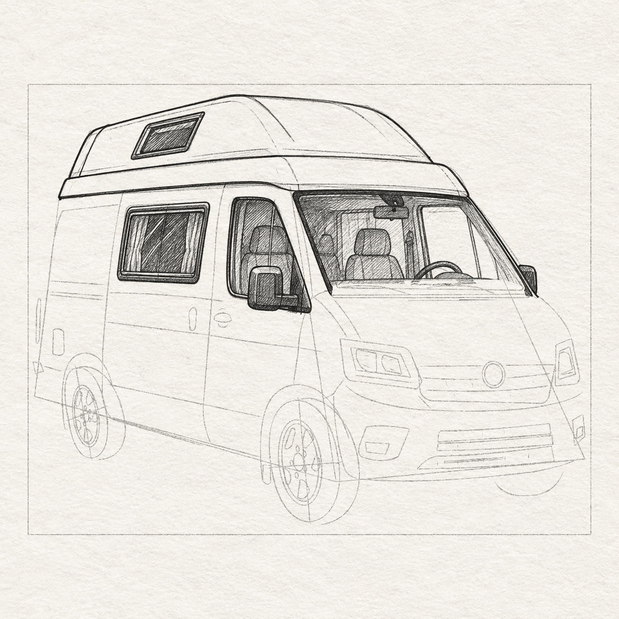
    1. The side-window seat is finished. Ink the large rounded windscreen headrest and widening back, then the partly hidden small seat. Stop backs at the dashboard and hidden sides at the window edges. Shade diagonally, leaving a lighter side edge and clear space beside the mirror.
    2. Ink the two chosen steering arcs, preserving their right-hand gap above the straight dashboard guide. The later curved dash rises behind that gap. Do not complete a hidden circle or merge arcs with seats.
    Rear interior frames and surrounding glass are inked behind the seats, while the bright right pane remains mostly white.
    Drawing 28B — the interior planes and windshield toneView larger

    Instructions for Drawing 28B — the interior planes and windshield tone
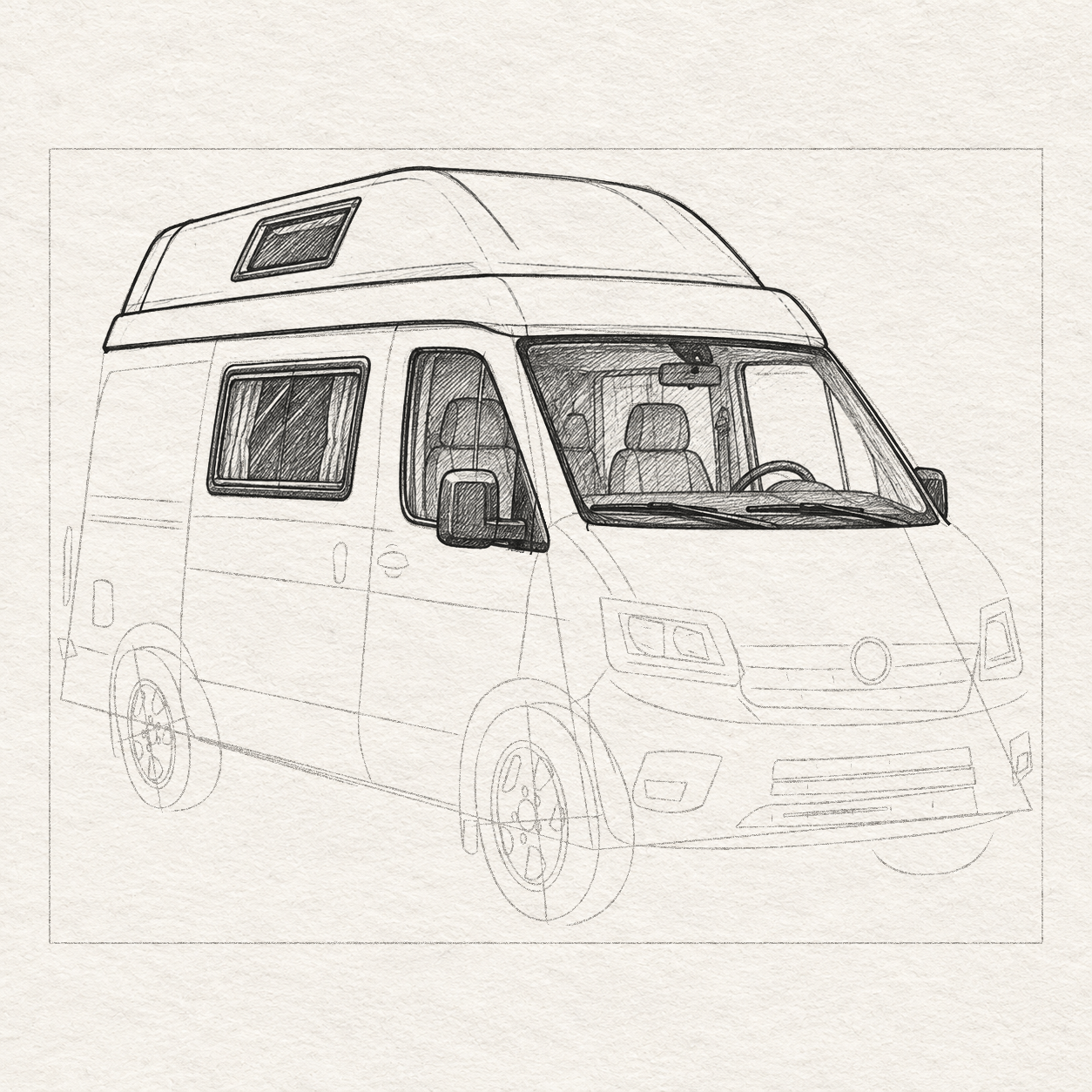
    1. Ink visible frame pieces of the rear opening and bright right pane, stopping behind seats, steering wheel and mirror. Shade nearly vertically inside the rear opening, with diagonal glass tone around it, darkest upper-left.
    2. Keep the broad right pane mostly white. Ink its fine edges and the two sloping strokes outside its right edge, staying inside the seal. Keep the seat, mirror and wheel readable; shading is not a new seam across the bright pane.
    Two slim wipers sit against a narrow dark dashboard strip whose upper edge bows behind the steering arcs.
    Drawing 28C — the dashboard and low wipersView larger
    Inked low wipers with short angled returns against the shaded dashboard strip and lower windscreen seal; the seat and steering shapes remain separate.
    Detail 28C.1 — Windscreen interiorEnlarged from this same step. The low blades and short returns are now inked against the dashboard strip; keep the blade edges distinct from the nearby seal.

    Instructions for Drawing 28C — the dashboard and low wipers

    1. Ink both low wipers as slim tapered shapes with angled returns. Add a second edge only for visible thickness. Leave thin bright gaps beside the blades and stop all ends at the seal, above the bonnet.
    2. Lightly freehand a shallow dashboard curve between the windscreen’s two lower inside corners. Keep it close to the straight dashboard guide, within about ¼ cm, and let it rise behind the steering arcs’ open right ends. Check the blade gaps, then ink the curve and shade the narrow strip below it.
    Next step — Ink the headlamps and reflectors

Chapter 6 — Ink the lights, wheels and body

8 steps · 15 progress drawings · Fineliner
  1. Step 29 of 38 · Fineliner

    Ink the headlamps and reflectors

    Both headlamps have inked frames and reflector details, with unequal lens widths, pale lower strips and small highlights.
    Drawing 29A — the lamp frames and reflectorsView larger
    Enlarged current near and far headlamp areas, preserving their exact frames and any reflector divisions introduced so far.
    Detail 29A.1 — Near and far headlampsEnlarged from this same step. Compare the wider near lamp with the compressed far lamp; the frames, inner divisions and pale lower strip are separate decisions in the stages that introduce them.

    Instructions for Drawing 29A — the lamp frames and reflectors

    1. Reserve the pale outer lips, broad lower strips and reflector highlights first. Ink both selected lamp frames and inset lens edges, rounding the lower corners. Darken each narrow frame surround between its outer frame and inset lens with close short strokes.
    2. Inside the wide lamp, ink the two unequal reflector pockets and short angled details, leaving their pale wedges and separating gap open.
    3. Darken the separator and a few lens-edge recesses with close short strokes.
    4. Ink the single narrow reflector shape selected inside the far lens. Add only a few short inside accents, leaving the lens border and pale lower strip clear.
    5. Stop darkening before either lamp’s highlights or lower strip disappear.
    Next step — Ink the upper grille and oval badge
  2. Step 30 of 38 · Fineliner

    Ink the upper grille and oval badge

    Dark grille slots are hatched around fine pale divider breaks, two light channels and the blank oval badge reserve.
    Drawing 30A — the upper grille slotsView larger
    Enlarged current upper grille and badge area, showing the actual channel spacing, retained guides and present reserves.
    Detail 30A.1 — Upper grille and badgeEnlarged from this same ink step. Keep the badge oval blank while filling the surrounding slots. Reserve the thin pale divider breaks first; do not cut the continuous lower channel behind the oval.

    Instructions for Drawing 30A — the upper grille slots
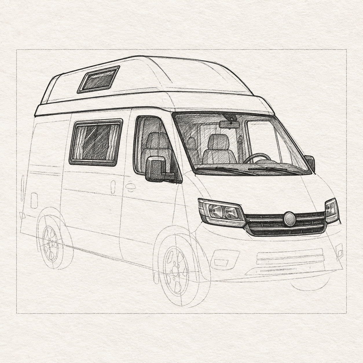
    1. Ink the upper grille’s rounded perimeter and slot edges. The upper light channel stops behind the badge; the lower continues below it. Reserve pale breaks around the short pencil marks inside each dark row; they are not black bars crossing a channel.
    2. Fill with close short strokes around those breaks, both light channels and the blank badge with its rim. Keep each break inside its row and leave clearance beside lamp frames and painted bumper.
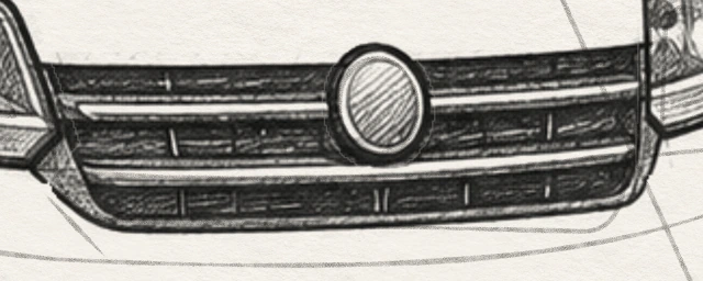
    A lightly hatched oval badge face is enclosed by a pale rim above the grille’s continuous lower channel.
    Drawing 30B — the small oval badgeView larger
    Enlarged current upper grille and badge area, showing the actual channel spacing, retained guides and present reserves.
    Detail 30B.1 — Upper grille and badgeEnlarged from this same step. The badge face is now hatched inside its pale rim, with a darker surrounding recess. The already inked lower grille channel remains continuous below it.

    Instructions for Drawing 30B — the small oval badge

    1. Ink the selected tilted badge oval, retaining the pale rim around its inner face. Darken the surrounding recess and add fine diagonals inside the face.
    2. Keep the upper channel hidden behind it and the lower visible below. Add no invented lettering; stop before face, rim and recess merge.
    Next step — Ink the fog pockets and intake rows
  3. Step 31 of 38 · Fineliner

    Ink the fog pockets and intake rows

    Small pale fog-light lenses remain inside unequal darker corner pockets, separate from the painted bumper.
    Drawing 31A — the fog-light recessesView larger
    Enlarged current near and far lower fog-light pockets and their differently compressed shapes.
    Detail 31A.1 — Lower fog-light pocketsEnlarged from this same ink drawing. The near pocket is wider than the far pocket. Keep each pale lens separate from its surrounding dark recess and the unshaded bumper.

    Instructions for Drawing 31A — the fog-light recesses
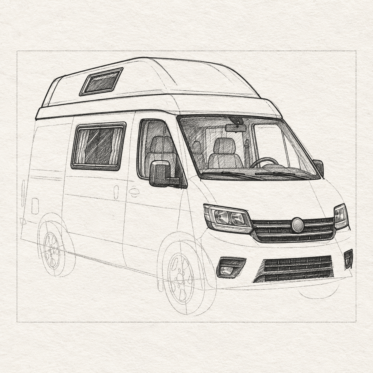
    1. Ink the rounded near pocket and its small pale lens low inside. Preserve the angled lower highlight, darkening only above and beside the lens with short diagonals.
    2. Repeat in the much narrower far pocket, keeping its little lens inside the curved right edge. Stop at pocket borders and leave the painted bumper gaps open.
    Three distinct lower intake slots are darkened around fine pale divider breaks, with a narrow bright accent inside the bottom row and separate adjacent diagonal tone.
    Drawing 31B — Ink three intake slotsView larger
    Enlarged three lower intake rows with the lower-left cap, separate painted gaps, divider locations and bottom interior bright reserve.
    Detail 31B.1 — Three lower intake rowsEnlarged from this same step. Keep the two painted gaps between the three rows distinct from the small divider breaks and the narrow bright reserve inside the bottom row.

    Instructions for Drawing 31B — Ink three intake slots

    1. Ink three separate closed rows, bowing their long edges without moving corners. Keep two continuous painted gaps and the bottom row’s farther-left rounded cap.
    2. Before filling, reserve pale breaks around pencil marks in every row and the narrow bright strip in the bottom row. Shade around them; never turn a divider into a black bar across a painted gap.
    3. Shade up-right in the triangle beside the rows’ left ends, between the upper-row left corner and the bottom row’s far-left tip. Stop before the fog pocket and keep the painted gaps white. Do not outline another row.
    Next step — Ink the smaller rear wheel
  4. Step 32 of 38 · Fineliner

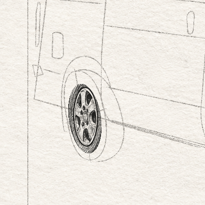
    Ink the smaller rear wheel

    The small rear rim has five dark openings, separate tiny bolts and pale metal bridges, with a narrow closely hatched dark ring immediately outside the pale metal lip; the wider tyre is still pencil.
    Drawing 32A — the rear rim and its openingsView larger
    Current small rear rim with pale lip and connecting metal bridges, five dark openings, tiny bolts and a narrow outside hatched ring, surrounded by remaining pencil tyre guides.
    Detail 32A.1 — Rear wheelEnlarged from this same step. The narrow dark ring lies outside the pale rim lip. Keep its close strokes separate from the five dark openings and tiny bolts inside the pale metal; the wider tyre and recess come in the next drawing.

    Instructions for Drawing 32A — the rear rim and its openings
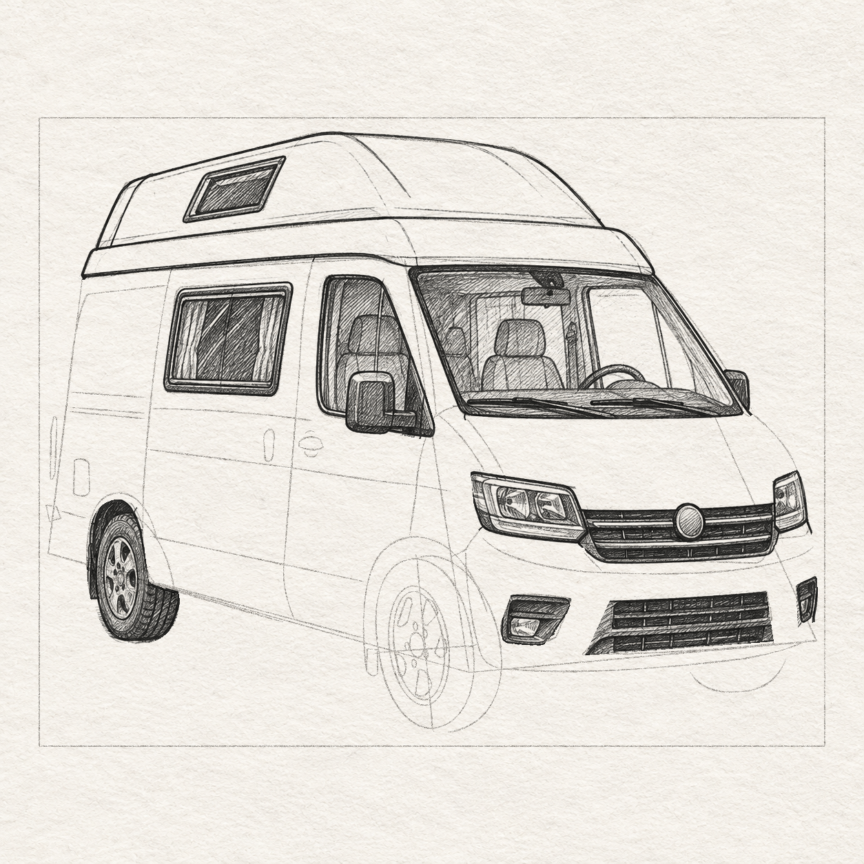
    1. Ink the small rim, inner lip and hub, keeping the pale lip and metal bridges open. Round and darken its five unequal openings and separate tiny bolts.
    2. Add only a few light strokes on the metal; tiny bolts may be simplified, but keep all five openings distinct. Keep the rim left of the tread and stop filling before hub-to-rim bridges disappear.
    3. Keep the metal lip and bridges pale. Immediately outside the pale metal lip, shade a narrow ring about 1–3 mm wide, well inside the larger tyre outline. Work around it with short, closely spaced pen strokes. The width and stroke count may vary slightly; stop before crossing into pale metal or filling the wider tyre face. Leave that wider face, the right-hand tread and the arch recess for Drawing 32B.
    Dark rear tyre rubber, exposed right-hand tread and a recessed arch gap surround the lighter rim, with a small attached contact patch below.
    Drawing 32B — the rear tyre and treadView larger
    Enlarged rear wheel from the current stage, showing the exact retained guides and current rim or tyre marks.
    Detail 32B.1 — Rear wheelEnlarged from this same step. Compare the rim, hub and outer tyre as separate nested forms; use the full view above for their position on the van. Keep the preceding narrow rim-surround ring; this view adds the broader tyre face, tread and separate arch recess.

    Instructions for Drawing 32B — the rear tyre and tread

    1. Keep the narrow dark ring from Drawing 32A. Ink the remaining tyre face outside it: fuller top, slightly flat contact at its established height. Add curved face strokes and block-like tread on the exposed right strip, preserving small pale breaks.
    2. Stop upper tread behind the side-panel sill; reserve the pale body return in front. Darken the wheel-well gap inside the arch while leaving its painted outer lip and metal rim clear.
    3. Darken the selected short lower arch return on the wheel’s left only to its existing end, leaving outside paper clear. Add short strokes directly under tyre contact; save the broad ground shadow for last.
    Next step — Ink the near wheel and exposed far tyre
  5. Step 33 of 38 · Fineliner

    Ink the near wheel and exposed far tyre

    The larger near rim has five dark openings, separate tiny bolts and pale metal bridges, with a narrow closely hatched dark ring immediately outside the pale metal lip; the wider tyre is still pencil.
    Drawing 33A — the near rim and openingsView larger
    Current larger near rim with pale lip and connecting metal bridges, five dark openings, tiny bolts and a narrow outside hatched ring, surrounded by remaining pencil tyre guides.
    Detail 33A.1 — Near wheel and body overlapEnlarged from this same step. The narrow dark ring lies outside the pale rim lip. Keep its close strokes separate from the five dark openings and tiny bolts inside the pale metal; the wider tyre and recess come in the next drawing.

    Instructions for Drawing 33A — the near rim and openings
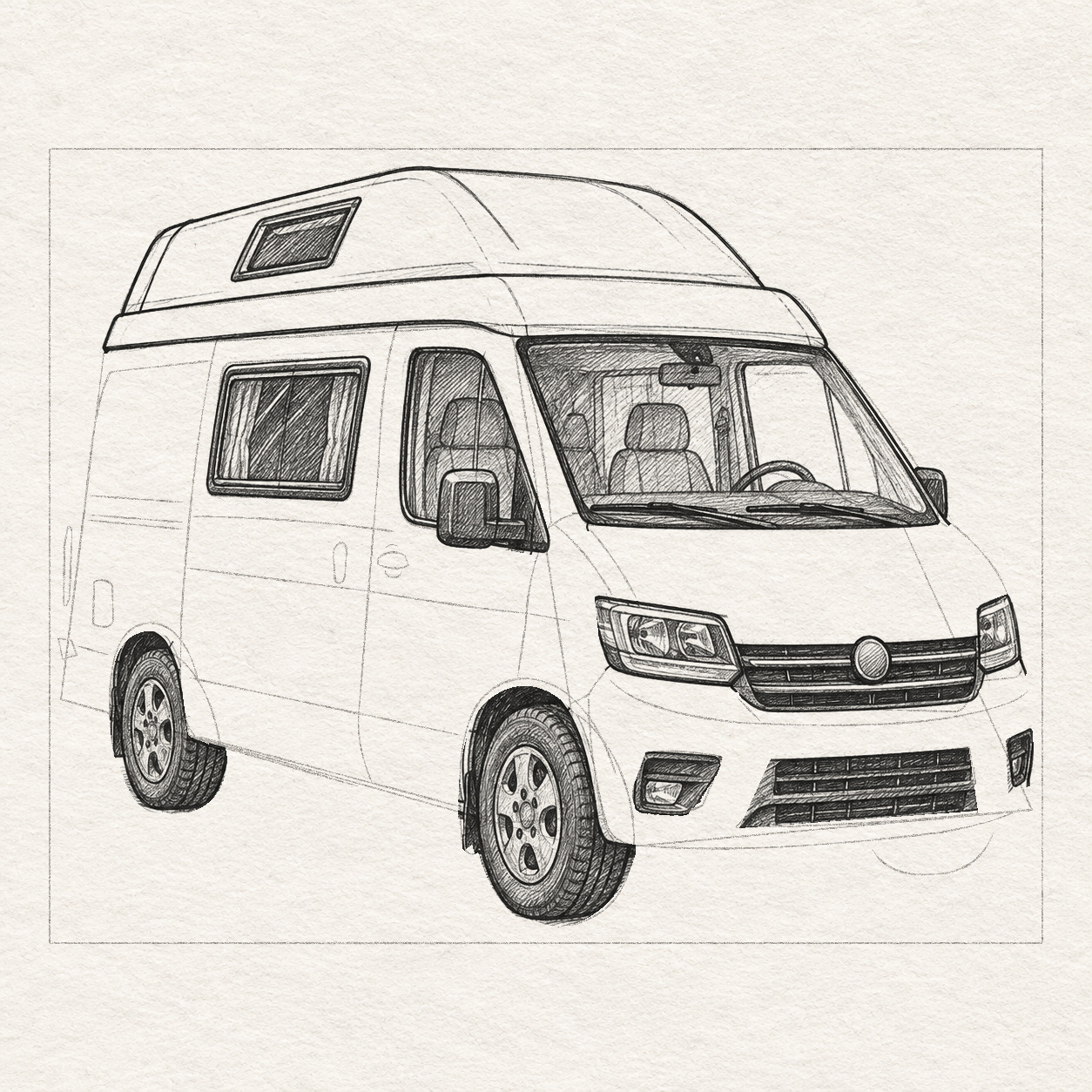
    1. Ink the large rim’s oval, hub and five unequal openings. Retain the pale metal lip and bridges joining hub to rim.
    2. Darken openings and tiny bolts with short strokes, preserving narrow highlights. Keep metal lighter than rubber. Stop before a pale bridge closes; do not enlarge a hole to hide a wobble.
    3. Keep the metal lip and bridges pale. Immediately outside the pale metal lip, shade a narrow ring about 1–3 mm wide, well inside the larger tyre outline. Work around it with short, closely spaced pen strokes. The width and stroke count may vary slightly; stop before crossing into pale metal or filling the wider tyre face. Leave that wider face, the right-hand tread and the arch recess for Drawing 33B.
    The near tyre’s exposed rubber and tread are inked with its dark recess and short lower return; the selected painted body overlap remains pale in front of the upper-right tread.
    Drawing 33B — Tyre, recess and lower returnView larger
    Enlarged near wheel from the current stage, including the rim, surrounding tyre and adjacent body overlap.
    Detail 33B.1 — Near wheel and body overlapEnlarged from this same step. Distinguish the rim and hub from the surrounding tyre and the separate body edge; the full view above preserves their placement. Keep the preceding narrow rim-surround ring; this view adds the broader tyre face, tread and separate arch recess.

    Instructions for Drawing 33B — Tyre, recess and lower return
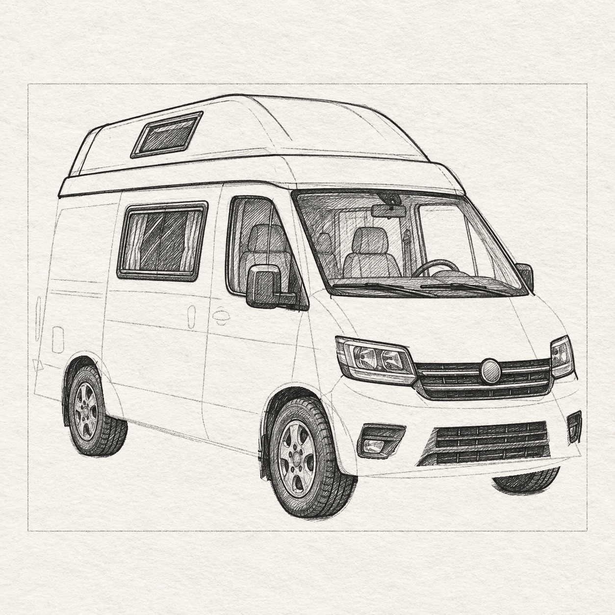
    1. Keep the narrow dark ring from Drawing 33A unchanged. Keep the painted overlap pale above/right of its chosen curve. That overlap hides the upper-right tyre guide. Ink only the remaining exposed rubber outside the ring, with a fuller top, flatter contact, curved sidewall strokes and staggered tread blocks. Keep the rim left of the right-hand tread strip.
    2. Darken the wheel recess but reserve its painted outer lip for the door. Fill the already enclosed lower arch return to its checked end, keeping outside paper clear: that return is attached bodywork, not rubber or ground.
    3. Add short contact strokes directly below this tyre. Keep its contact lower than the rear wheel’s and leave broad ground shading until last.
    A shallow treaded far-tyre sliver is inked below the front body, with its upper portions hidden and a small contact patch beneath.
    Drawing 33C — only the visible far tyreView larger

    Instructions for Drawing 33C — only the visible far tyre

    1. Ink only the shallow arc exposed below the bumper, with both ends disappearing behind the body. Inside that sliver, first reserve the narrow curved light strip, then add curved tread strokes around it by eye. Invent no complete rim and draw nothing through painted bodywork.
    2. Add a few short strokes under its lowest contact. Leave wider ground shading for the final step.
    Next step — Ink the rear and sliding side panels
  6. Step 34 of 38 · Fineliner

    Ink the rear and sliding side panels

    The rear body edge, panel inset, rubbing strip, filler hatch and narrow rear light are inked beside the rear wheel.
    Drawing 34A — the rear side panel and its fittingsView larger
    Enlarged current inked rear filler hatch, latch, rear light and short lower return.
    Detail 34A.1 — Rear fittingsEnlarged from this same step. The hatch, right-edge latch and narrow rear light are now inked. Keep their pale interiors distinct from the fine panel edges and local hatch.

    Instructions for Drawing 34A — the rear side panel and its fittings
    1. Ink the rear body edge and rounded blank-panel inset to the arch, not the old box’s sharp corners. Add the thin rubbing strip, filler hatch with right latch, and rear-light sliver as separate fittings.
    2. Shade below the strip with spaced diagonals, denser near the lower edge; keep the upper panel pale.
    3. Ink the pale arch lip beside the dark recess, leaving that recess and short return’s dark interior unchanged. Add only the return’s selected fine outside edge, never extending into the ground. Keep the filler hatch clear of the arch.
    Curved sliding-door seams, a tall handle and a thin lower strip surround a lightly hatched painted panel below the side window.
    Drawing 34B — the sliding door and lower sillView larger
    Enlarged current tall sliding handle beside the still-pencil short cab handle and rounded backing.
    Detail 34B.1 — Door handles and backingEnlarged from this same step. Ink the tall sliding handle in this stage; the short cab handle and its backing remain pencil until the next cab-panel stage.

    Instructions for Drawing 34B — the sliding door and lower sill

    1. Ink the sliding-panel seams and sill, stopping at window and arches. Add the tall handle left of its front seam. Shade diagonally below the window, denser at the sill but lighter than the glass.
    2. Find the selected sloping line joining the bottoms of the door seams toward the large arch. Draw the bottom strip’s outside edge ⅛ cm below that line, connect its ends to the existing body turns, then shade its narrow underside.
    3. Ink the fine upper line from 2.8 cm across and 7.4 cm down to the front door seam near 6.5 cm across and 7.65 cm down, and lower line from 2.7 cm across and 8.45 cm down to 6.45 cm across and 8.9 cm down. Keep both finer than seams and separate from diagonal shading.
    Next step — Join the cab door to the bonnet
  7. Step 35 of 38 · Fineliner

    Join the cab door to the bonnet

    The cab panel’s seam, handle, pale arch lip, two fine body-line continuations and lighter outer body-side turn are inked beside the retained dark wheel recess and lower return. The short cab bar crosses rounded backing ends visible above and below it.
    Drawing 35A — the cab door and arch lipView larger
    Enlarged current inked tall sliding handle, short cab handle and rounded backing.
    Detail 35A.1 — Door handles and backingEnlarged from this same step. Ink the horizontal cab bar across the pale upright backing, preserving its rounded top and bottom ends. The tall sliding handle is retained from the previous stage.

    Instructions for Drawing 35A — the cab door and arch lip
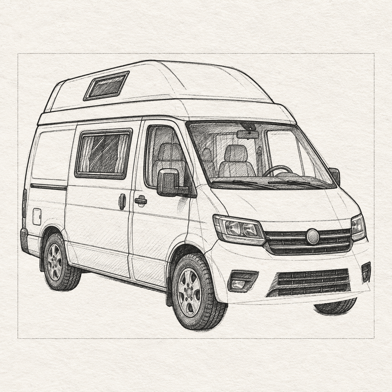
    1. Select the rounded upper cab-door outline now; the earlier outside positioning guide is not the line to trace. Start on the roof band at the front sliding-door seam, just left of the cab-window frame. Freehand a shallow top about 3 mm above the frame, then round down-right outside its steep front edge, narrowing the pale gap to about 1–2 mm. Keep inside the light outside guide and ink this chosen route only as far as the mirror. Below the mirror, ink the retained lower cab-door guide down to the large arch. Keep the mirror break open. Leave the pale arch lip beside the existing dark recess.
    2. Continue the fine upper line only to 7 cm across and 7.7 cm down, beside the cab pane. Continue the lower through 9.6 cm across and 9.35 cm down to 10.6 cm across and 9.5 cm down, left of the near lamp.
    3. Ink the outer body-side turn from cab seam toward lamp, leaving the inner bonnet curve in pencil for Drawing 35B. Ink the short join above the cab pane’s lower-front corner up to the outside windscreen seal, stopping at the seal.
    4. Continue that same narrow bottom strip below the cab door to the large arch. Keep its outside edge ⅛ cm below the selected line from the lower door-seam turn, then add only light panel shading and the attached underside. You may round the existing dark arch return’s tiny bottom tip beside the large tyre with one small pen touch. Keep its length and position; add no bar or bridge to the tyre.
    5. Ink the short handle bar across its backing, leaving both pale rounded backing ends visible. The lower end is an outline, not hatching.
    The inner near and far bonnet contours meet the lamp frames, while a shallow cross-front edge joins the lamps above the grille and the broad bonnet surface stays light.
    Drawing 35B — the bonnet contours and light surface strokesView larger

    Instructions for Drawing 35B — the bonnet contours and light surface strokes

    1. Ink the inner near bonnet curve from beside the lower-left glass to the near lamp, separate from the outer body-side curve on its left. Ink the far curve from the painted pillar’s outside base to far lamp, keeping both existing joins fixed.
    2. Add only a few fine surface-turn strokes near the sides, stopping before lens and grille interiors; keep the broad centre light.
    3. Rehearse, then freehand the real front edge in ink between the lamp turns: from 13.65 cm across and 9.4 cm down, bow down through 16.1 cm across and 9.5 cm down, then rise to 18.65 cm across and 9.25 cm down. This shallow sweep above badge and grille is a boundary, not optional shading or a straight new seam.
    Next step — Ink the bumper and complete the front overlap
  8. Step 36 of 38 · Fineliner

    Ink the bumper and complete the front overlap

    Bowed bumper contours and fine body returns enclose the existing dark openings, with pale painted lips and restrained diagonal tone.
    Drawing 36A — the painted bumper around its openingsView larger
    Enlarged current inked fine outside-left grille return, pale separation from the thick grille border and join to the upper body-turn contour.
    Detail 36A.1 — Fine return beside the grilleEnlarged from this same ink step. The fine return curves into the upper body-turn line, with a pale gap beside the thicker grille frame. Keep that gap open while inking the continuous curve.

    Instructions for Drawing 36A — the painted bumper around its openings

    1. Ink the selected shallow lower bumper curve and its turns around the lamps, fog pockets and intake. Keep the pale painted strips between openings.
    2. At the near corner, curve back toward the arch instead of making a sharp box corner.
    3. Add short diagonal lower-bumper shading, denser below its projecting edge. Keep the upper strip and opening lips light, with a narrow attached underside shadow.
    4. Where the bumper hides the far tyre, finish only the remaining dark upper tyre strip below that body edge. Keep its earlier lower arc and tread unchanged.
    5. Ink the selected upper surface line below the grille, continuing toward the far lamp corner. Keep it separate from the grille’s thick lower border.
    6. Ink the separate fine curve outside the grille’s lower-left corner all the way into that upper body line, leaving a pale gap beside the thick grille frame.
    7. Ink the near painted-body overlap beside the large tyre, joining the existing return bend to the lower bumper. Keep its light body patch above/right and the existing rubber below/left.
    8. Do not trace the hidden upper tyre guide through that patch. Leave the broad fading ground shadow for the final step.
    Next step — Dry-test the ink and erase the pencil

Chapter 7 — Dry, erase and add the shadow

2 steps · 2 progress drawings · Erase
  1. Step 37 of 38 · Erase

    Dry-test the ink and erase the pencil

    The camper’s permanent fineliner work remains after the working box, wheel axes and all other light pencil construction are erased.
    Drawing 37A — Let the ink dry, then lift the pencilView larger

    Instructions for Drawing 37A — Let the ink dry, then lift the pencil

    1. Let the fineliner dry. Make a similar dark patch on scrap paper and test it gently with the eraser.
    2. If the test smears, wait longer. When it stays clean, erase the guide box, body-plane lines, roof guides, wheel crosses and remaining pencil.
    3. Use small gentle passes and brush away crumbs. Keep the inked outlines, pale frame lips and metal bridges unchanged.
    4. Compare roof, rims, windows and seams before and after. Erasing removes pencil; it cannot move a wrong permanent ink line.
    Next step — Add the fading ground shadow
  2. Step 38 of 38 · Fineliner

    Add the fading ground shadow

    The finished fineliner camper rests on a fading diagonal ground shadow attached to its three tyre contacts, with clear textured paper beyond.
    Drawing 38A — Anchor the tyres with a ground shadowView larger

    Instructions for Drawing 38A — Anchor the tyres with a ground shadow

    1. After the ink is dry and pencil erased, start the ground shadow at the three tyre contacts and beneath the van.
    2. Keep it darkest at those contacts. Pull short diagonal strokes outward, making them lighter and farther apart toward the edges.
    3. Let the shadow fade into clear paper, especially below the large wheel. Do not enclose it in a rectangle or add a floating patch.
    4. Keep rim and tread readable, and stop well before the paper edge. Individual stroke ends may vary; paper fibres do not need copying.
    Back to the chapters

If something looks off

The van looks twisted before I reach the details

Return to the six plane-corner marks and compare the long side with the narrower front. Then compare the two wheel centers and contacts. Correct the light scaffold before ink; do not fix a wrong body width by stretching one window.

The wheels look like circles pasted onto the side

Recheck their four tips and different apparent sizes. Keep the face left of its tread-depth strip, inset the narrow tilted rim, and preserve metal bridges around the openings. The rear contact sits higher on the page than the near contact.

Dark frames and hatching merge into black blocks

Reserve the pale frame lips, glass gaps and rim bridges before dark strokes. Add tone in short passes with pauses to compare the remaining white paper. Stop before the openings lose their separate borders.

A contour does not exactly match the initial guide

The straight planes, outer bounds and wheel diameters locate the observed forms. Round a lamp corner, reshape the tyre contact or clip an interior line where the step says, rather than tracing the entire envelope. Make that decision in pencil before permanent pen.

Tiny details are difficult at my drawing size

Use the View larger image link to inspect the reference. At a small scale simplify bolt interiors to dots and vary individual tread/hatch marks, while retaining the five main rim openings, mirror attachments, lamp divisions and separate grille rows.