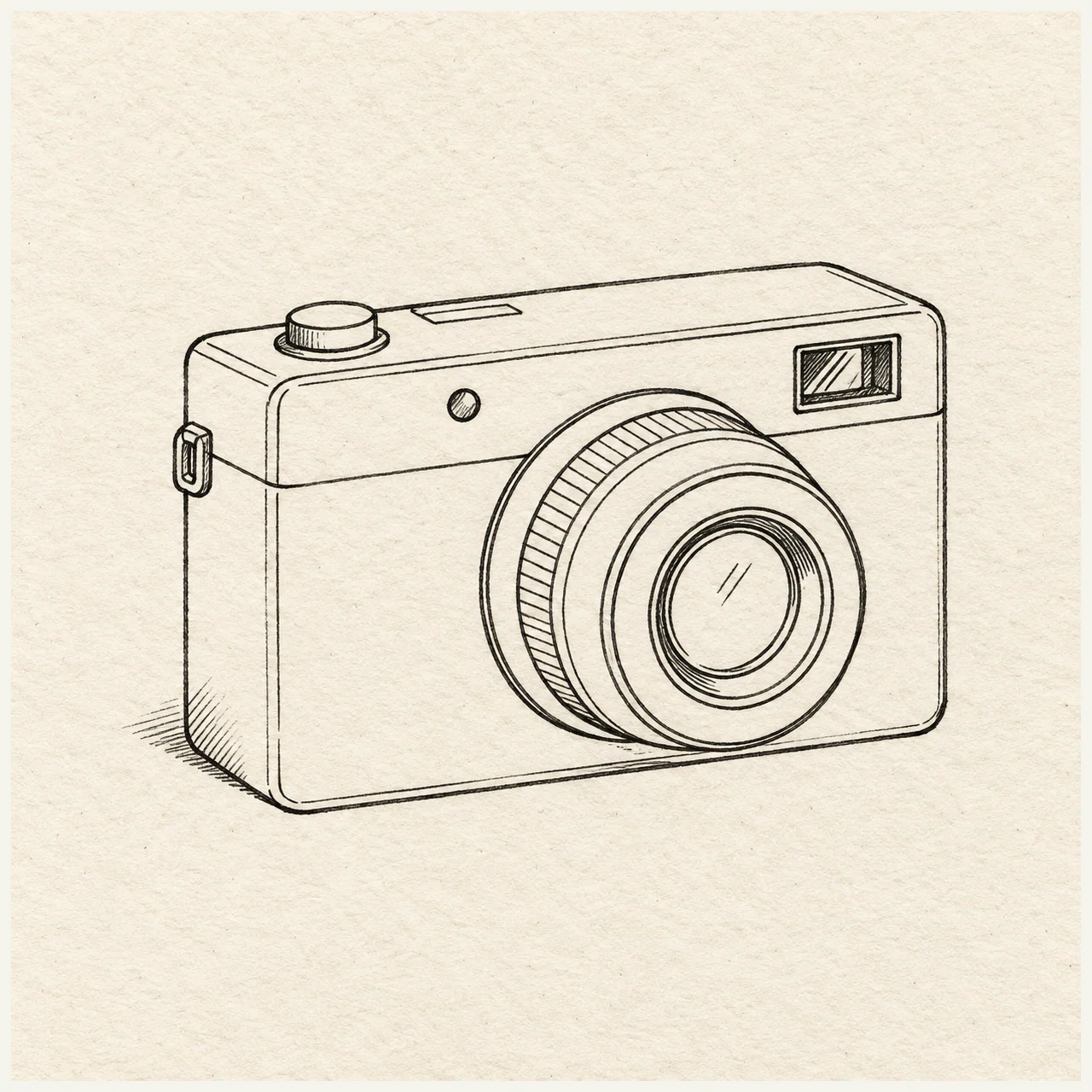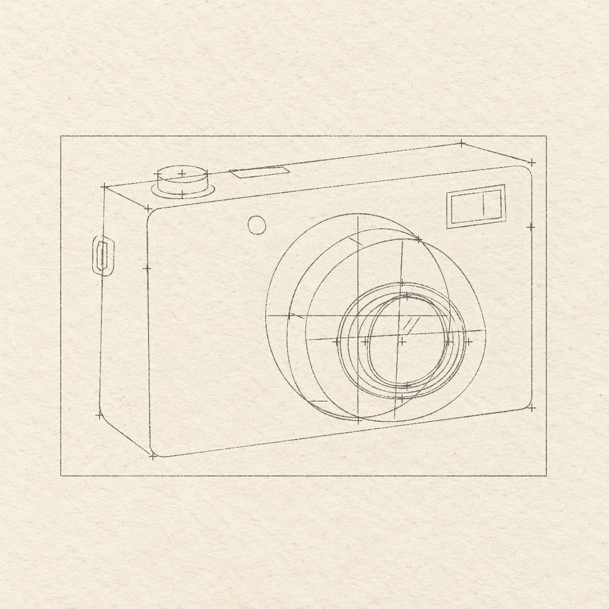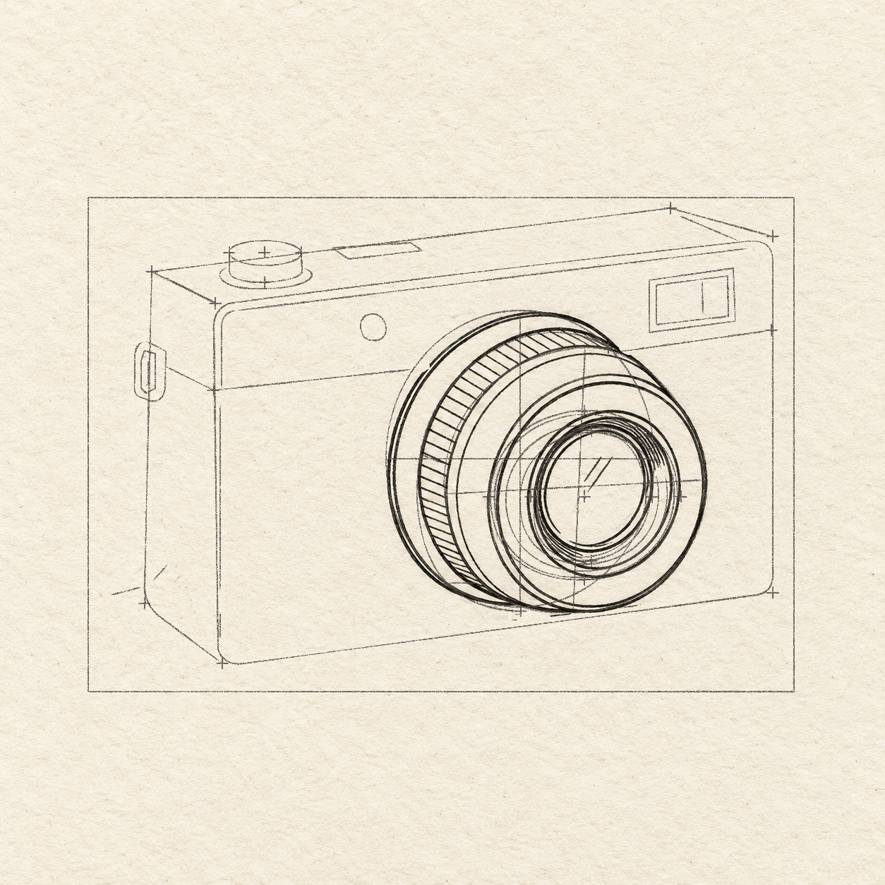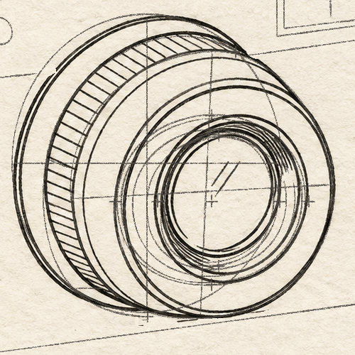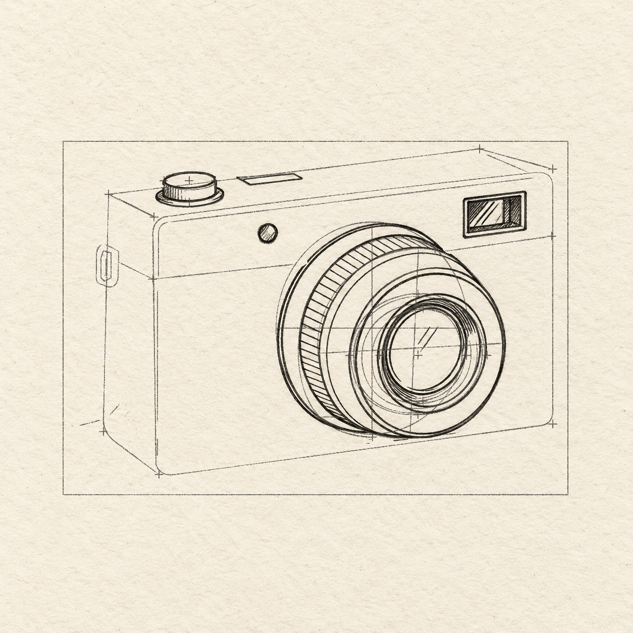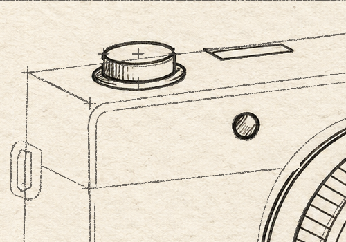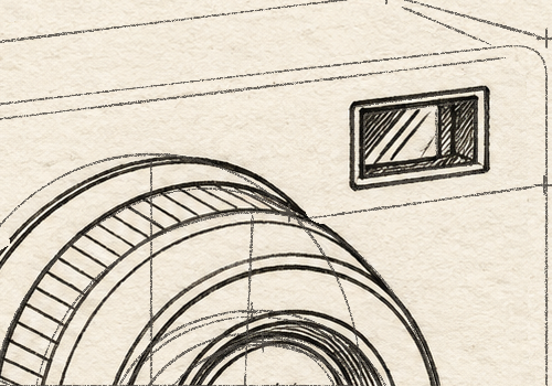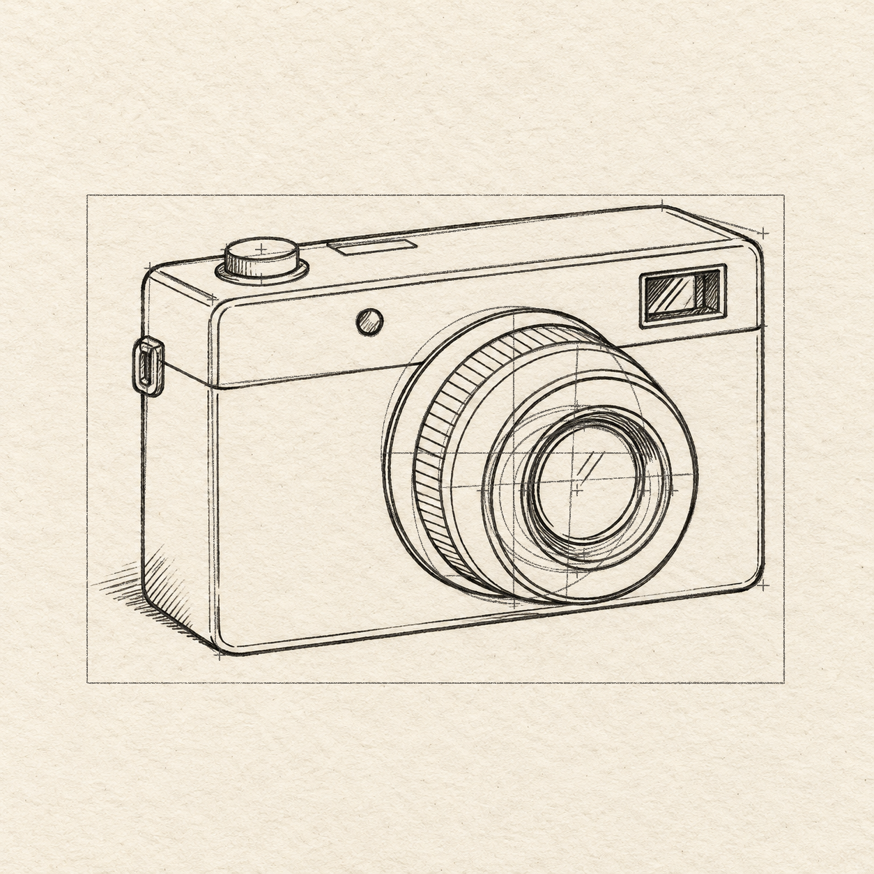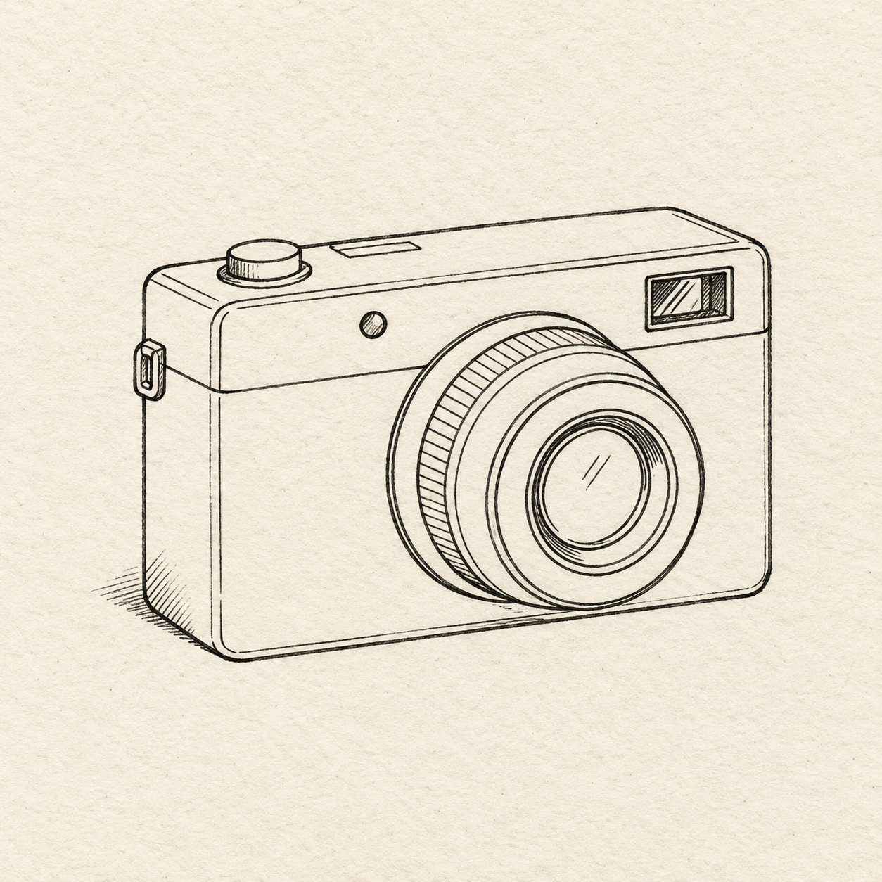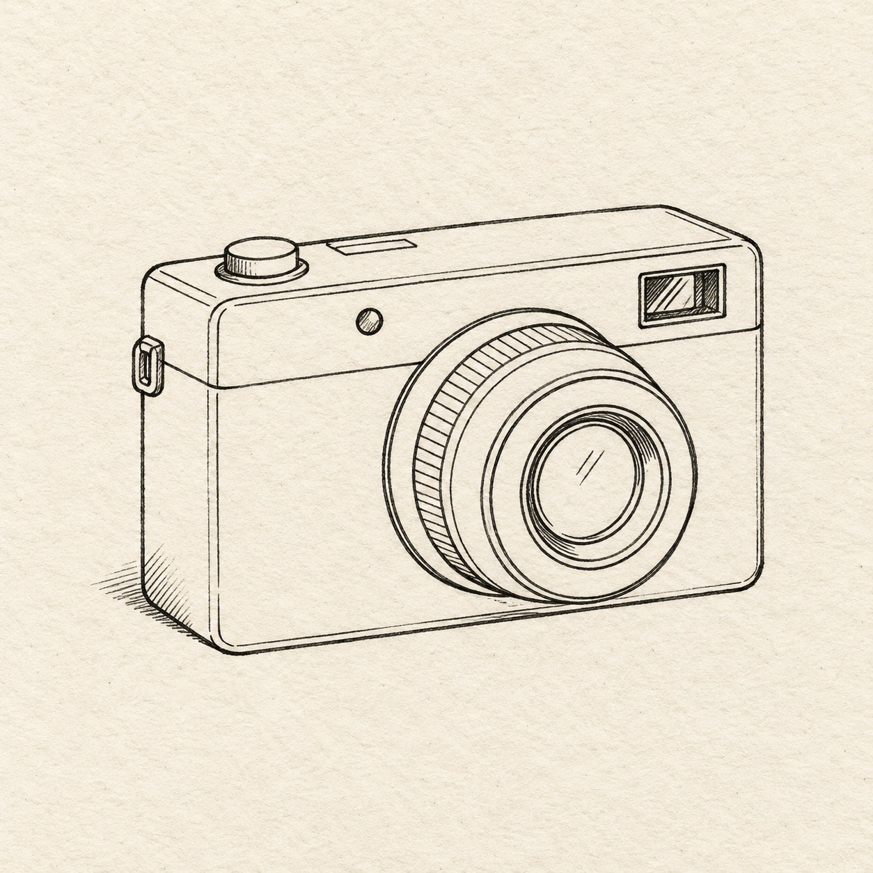
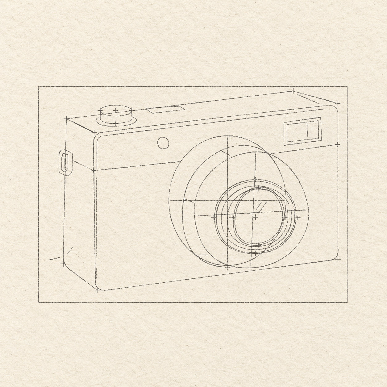
One compact camera in three-quarter view, box body, central cylindrical lens and top shutter button; no brand or lettering. Black and gray fineliner drawing on warm textured sketchbook paper.
Drawing referenceAbout reference use

Camera fine ink study

One compact camera in three-quarter view, box body, central cylindrical lens and top shutter button; no brand or lettering. Practice clear contours and a few local shadows in fine ink.

Everyday objectsEasyFinelinerReference practice: about 20 min
Save reference

Follow the drawing tutorial

Construct this three-quarter camera with measured plane limits, separately placed lens envelopes and sparse fittings, then ink the prepared forms and add bounded hatching.

Start the 11-step tutorial

A small thing to tryKeep the lens ellipses aligned with the front face.

Draw it, one step at a time

How to Draw a Camera in Fineliner

Construct this three-quarter camera with measured plane limits, separately placed lens envelopes and sparse fittings, then ink the prepared forms and add bounded hatching.

11 steps · 20 progress drawings Full tutorial: about 55 minutes, at your pace

What you’ll need

  • HB pencil
  • Fine black fineliner
  • Soft eraser
  • Ruler marked in centimetres and millimetres
  • Matching scrap paper for the ink-dry test
  • Paper with room for a movable 10 cm by 7 cm working rectangle and comfortable margins

Before you start

Place the whole working rectangle where you want the study on your sheet. Across means right and down means toward the bottom, measured from that rectangle’s top-left corner unless another existing mark is named. Keep every construction and rehearsal line light. Use the ruler for stated straight directions; rehearse rounded curves above the paper and draw them freehand between their physical limits. Correct misplaced light pencil before ink. Named Drawings show their nearby actions completed; Details show the same stage more closely.

  1. Step 1 of 11 · Pencil

    Place the camera’s three planes

    One light ten-centimetre wide, seven-centimetre high working rectangle on warm paper; no camera marks yet.
    Drawing 1A — Movable camera working boxView larger

    Instructions for Drawing 1A — Movable camera working box
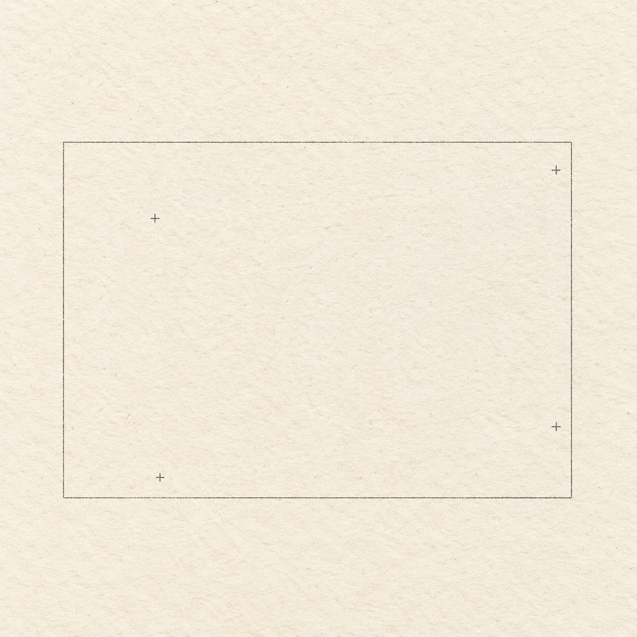
    1. Choose where you want the camera on your sheet. With a ruler and light HB pencil, draw a working rectangle 10 cm wide and 7 cm high: make the top edge, both downward sides, then join the lower ends. Leave comfortable paper margins around it. Compare Drawing 1A — Movable camera working box.
    Four small crosses mark the sloping front face’s upper and lower corner limits; the right side is higher than the left.
    Drawing 1B — Front face corner limitsView larger

    Instructions for Drawing 1B — Front face corner limits
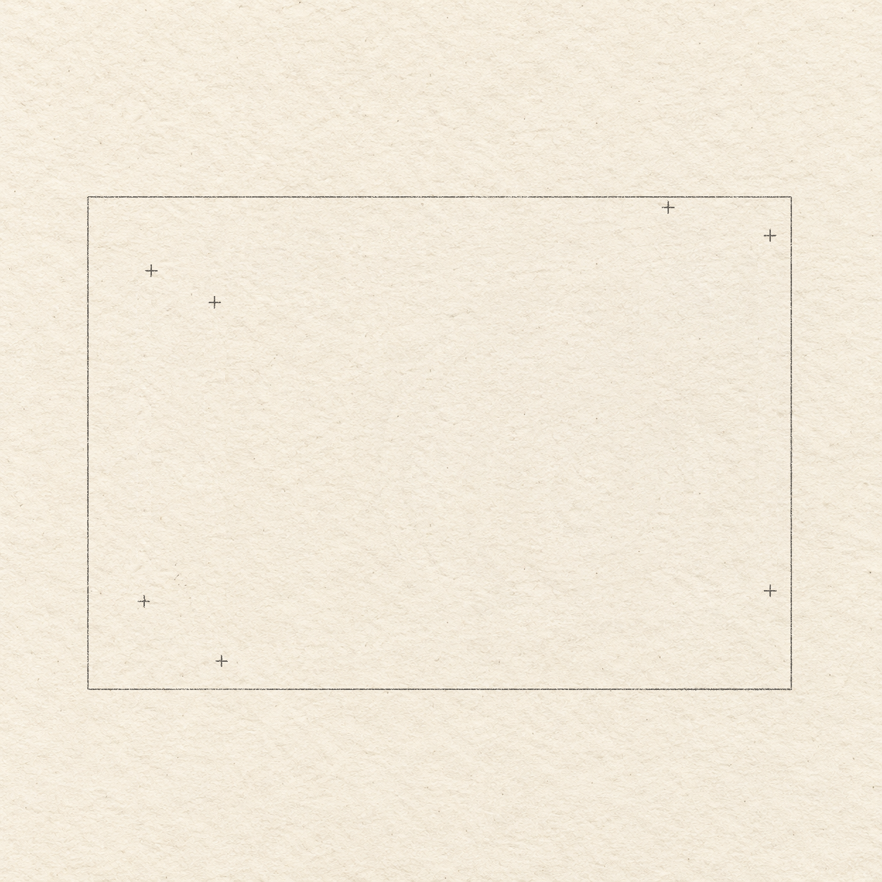
    1. Use two light 2 mm strokes for each cross, crossing at the measured point. Measure from the box’s top-left corner. Mark the front face’s upper-left corner limit 1.8 cm across and 1.5 cm down, then its upper-right limit 9.7 cm across and 5.5 mm down. Joining these two limits will give the top edge its upward-right slope.
    2. Mark the lower-left limit 1.9 cm across and 6.6 cm down, and the lower-right limit 9.7 cm across and 5.6 cm down. Keep all four crosses light. They locate the front face; its finished corners will be rounded, not sharp. Compare Drawing 1B — Front face corner limits.
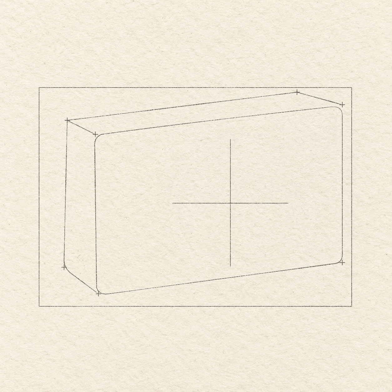
    Three additional crosses locate the back-left top corner, back-right top corner and lower back-left corner, behind the existing front face.
    Drawing 1C — Top and left depth limitsView larger

    Instructions for Drawing 1C — Top and left depth limits
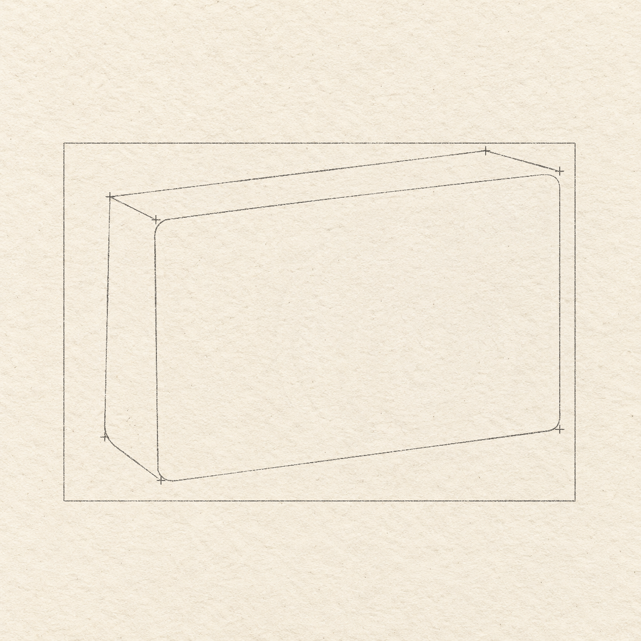
    1. Mark three back-corner limits from the box corner: upper-left 9 mm across and 1.05 cm down; upper-right 8.25 cm across and 1.5 mm down; lower-left 8 mm across and 5.75 cm down. These set the shallow top and left sides behind the front face. Compare Drawing 1C — Top and left depth limits.
    A complete light rounded front case joins the four front limits, with shallow top and left depth planes behind it. All corner crosses remain.
    Drawing 1D — Complete light case constructionView larger

    Instructions for Drawing 1D — Complete light case construction

    1. Join the four front-face limits with light, nearly straight pencil edges, using a ruler to set their slopes. Round the corners freehand instead of drawing sharp angles: allow about 3 mm at the upper-right turn and 1–2 mm at the others. Let the long top edge bow very slightly, staying within 1 mm of the straight slope between its two corner limits. Keep this complete front outline light; the lens and fittings will overlap parts of it.
    2. From the front upper-left limit, draw a light line back to the upper-left back cross. Join that cross to the upper-right back cross, then connect down-right to the front upper-right limit. Follow those existing points; do not redraw the front top edge you already made.
    3. From the upper-left back cross, draw down toward the lower-left back cross, rounding that lower turn slightly. Continue down-right to the front lower-left corner. Follow these two new edges to complete the left side; keep the previously drawn shared edges unchanged. Compare Drawing 1D — Complete light case construction.
    Next step — Place the separate lens envelopes
  2. Step 2 of 11 · Pencil

    Place the separate lens envelopes

    One light measured cross locates the rear lens envelope on the front face, distinctly left and above the later front lens.
    Drawing 2A — Rear lens width and heightView larger

    Instructions for Drawing 2A — Rear lens width and height
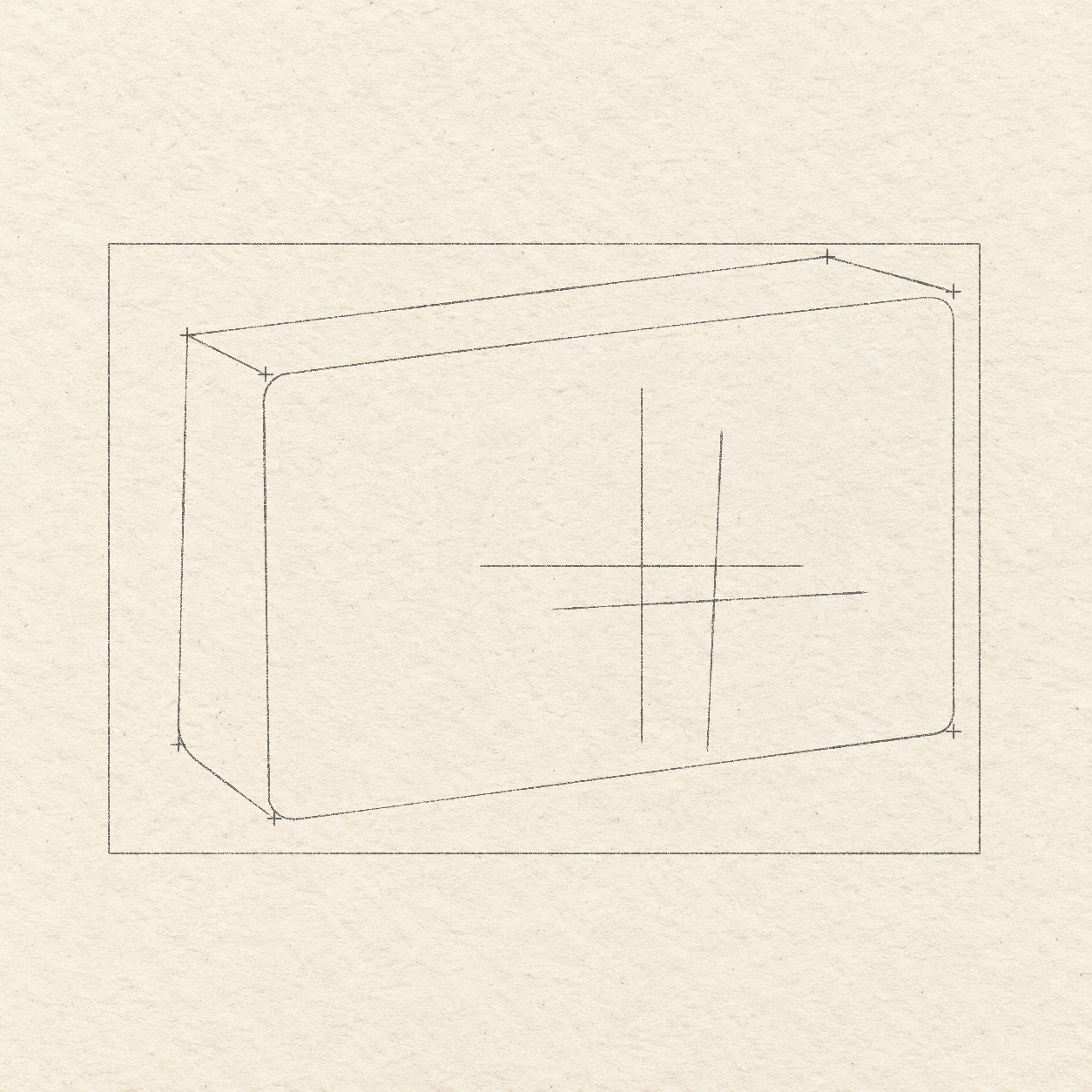
    1. From the working box corner, locate the rear lens center about 6.1 cm across and 3.7 cm down. Through it, draw a light level line 3.8 cm long and an upright line 4.2 cm long, centered on the same point. Their four ends bound the rear lens envelope; they are not case seams. Compare Drawing 2A — Rear lens width and height.
    Two light slightly tilted guide lines connect the front lens’s four measured extremes, separate from the earlier rear cross.
    Drawing 2B — Front lens tilted limitsView larger

    Instructions for Drawing 2B — Front lens tilted limits
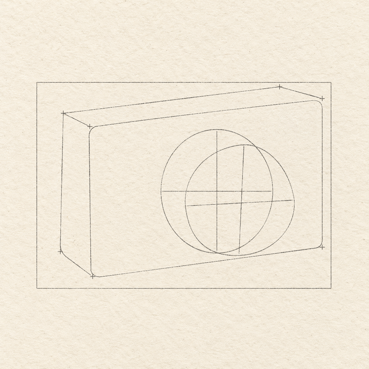
    1. For the front lens, mark its left extreme about 5.05 cm across and 4.2 cm down from the box corner, and its right extreme 8.75 cm across and 4 cm down. Join those two points with a light straight line. It rises about 2 mm toward the right.
    2. Mark the front lens’s top about 7.05 cm across and 2.1 cm down, then its bottom 6.85 cm across and 5.9 cm down. Join these two with a light line; it leans slightly left as it descends. These are opposite curve limits, not edges of a rectangular lens. Compare Drawing 2B — Front lens tilted limits.
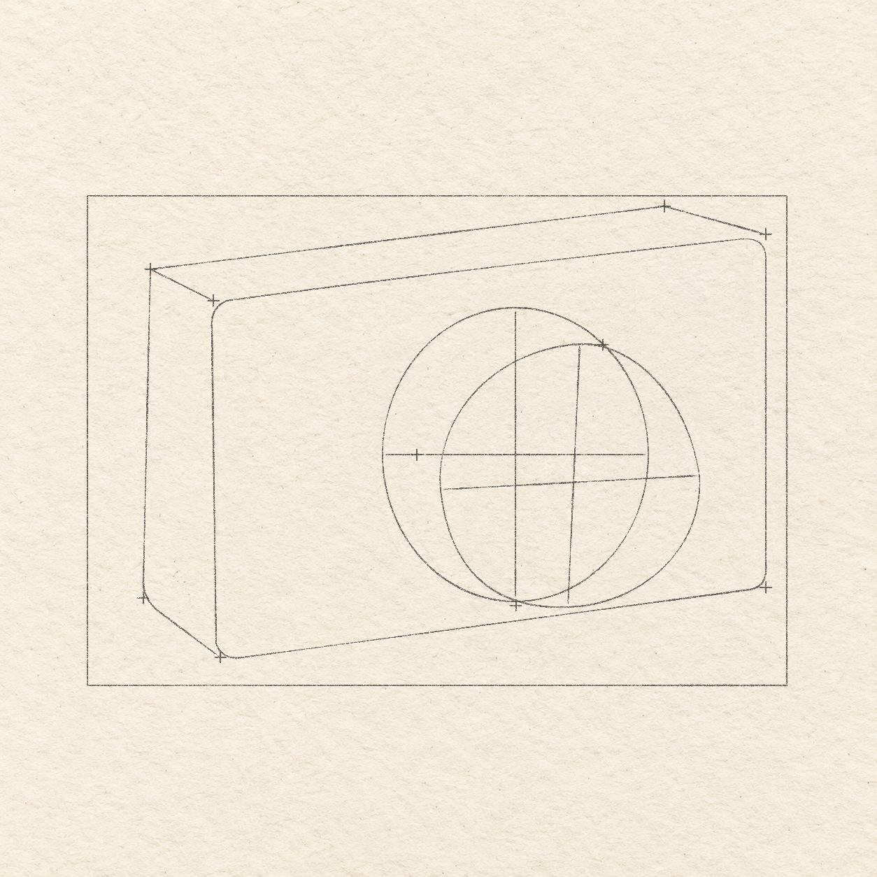
    Two overlapping light lens envelopes retain different centers: the rear envelope sits farther left and up, while the front face is lower and right.
    Drawing 2C — Rear and front lens envelopesView larger

    Instructions for Drawing 2C — Rear and front lens envelopes

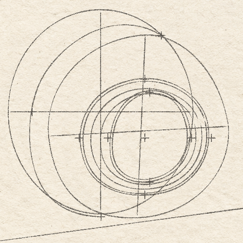
    1. Round a light freehand oval through the rear cross’s four ends. Rehearse the curve above the paper, then join the left, top, right and bottom limits smoothly. This full oval plans the back of the barrel; part of it will be hidden by the front lens.
    2. Join the front guide’s four limits with a light rounded curve, drawing freehand and preserving their slight tilt. Keep its leftmost turn near the left limit rather than forcing a circle centered on the rear cross. Leave both sets of straight guides visible. Compare Drawing 2C — Rear and front lens envelopes.
    Next step — Sketch the ribbed barrel enclosure
  3. Step 3 of 11 · Pencil

    Sketch the ribbed barrel enclosure

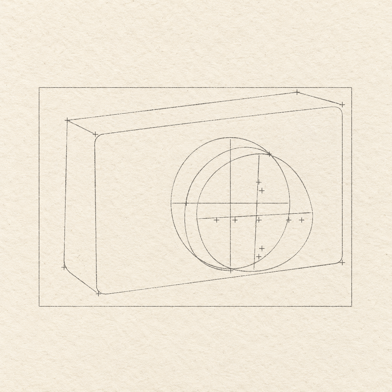
    Three small crosses locate the upper and lower joins and the middle passage of the ribbed-strip curve between the existing lens envelopes.
    Drawing 3A — Three ribbed-strip curve supportsView larger

    Instructions for Drawing 3A — Three ribbed-strip curve supports
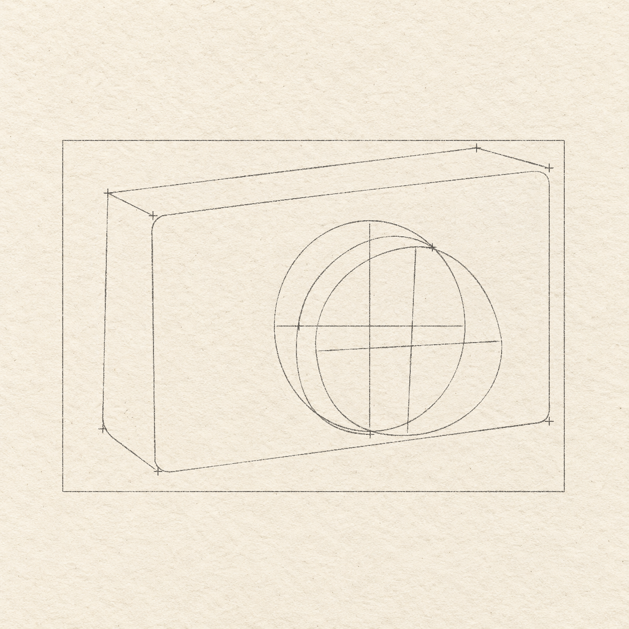
    1. Mark a cross 3 mm right of the front lens’s top limit. Mark another 7.5 mm left of its bottom limit, at that same lower height. These are the two ends of the new barrel curve.
    2. On the rear lens’s horizontal guide, mark a cross 5 mm right of that line’s left end. The new curve will pass through this middle cross, between its two end crosses. Compare Drawing 3A — Three ribbed-strip curve supports.
    A light curved rim joins its three physical support crosses between the earlier lens envelopes, defining the future ribbed strip.
    Drawing 3B — Ribbed barrel enclosure sketchView larger

    Instructions for Drawing 3B — Ribbed barrel enclosure sketch

    1. From the upper new cross, curve gently up-left, rising about 2 mm above it. Sweep down-left through the middle cross, then round down-right to the lower new cross. Rehearse this freehand arc before drawing it lightly. Together with the front-face curve, it bounds the strip that will carry the short ribs. Compare Drawing 3B — Ribbed barrel enclosure sketch.
    Next step — Plan the inner rings and opening
  4. Step 4 of 11 · Pencil

    Plan the inner rings and opening

    Small crosses set the inner lens ring’s center and four limits, plus the smaller opening limits inside it.
    Drawing 4A — Inner ring and opening limitsView larger

    Instructions for Drawing 4A — Inner ring and opening limits
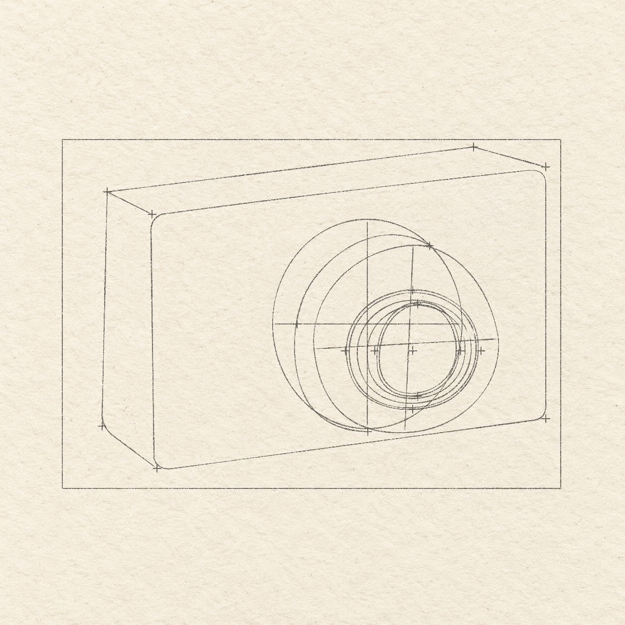
    1. From the box corner, mark the inner ring’s center about 7 cm across and 4.25 cm down. Mark its left and right limits 1.35 cm to either side of that center, and its top and bottom about 1.2 cm above and below. This smaller ring sits inside the front face.
    2. For the smaller opening, use a center about 1 mm right of the inner ring center, at the same height. Mark its side limits about 8.5 mm either way and its top and bottom about 9 mm above and below. Keep all these small marks light. Compare Drawing 4A — Inner ring and opening limits.
    Light curved inner ring and opening routes follow their measured limits, with parallel rim curves leaving pale bands between them.
    Drawing 4B — Inner rings and reserved openingView larger
    This is the same drawing at a closer scale. Distinguish the intermediate barrel curve, the front-face boundary and the smaller ring/opening; keep their separate paper spaces.
    Detail 4B.1 — Lens boundaries and pale bandsThis is the same drawing at a closer scale. Distinguish the intermediate barrel curve, the front-face boundary and the smaller ring/opening; keep their separate paper spaces.

    Instructions for Drawing 4B — Inner rings and reserved opening

    1. Round the inner ring freehand through its four limits. Add a close companion curve about 1 mm inside it, keeping a slim pale strip between the two. Use short light passes to correct a flat turn before ink; this is a ring, not a filled disk.
    2. Round the smaller opening through its own four limits, then add a close second curve around its edge. Keep the central opening as paper. Sketch a few short curved passes along the narrow rim, reserving a pale strip between this darkening band and the larger ring. Compare Drawing 4B — Inner rings and reserved opening.
    Next step — Plan ribs and reflections
  5. Step 5 of 11 · Pencil

    Plan ribs and reflections

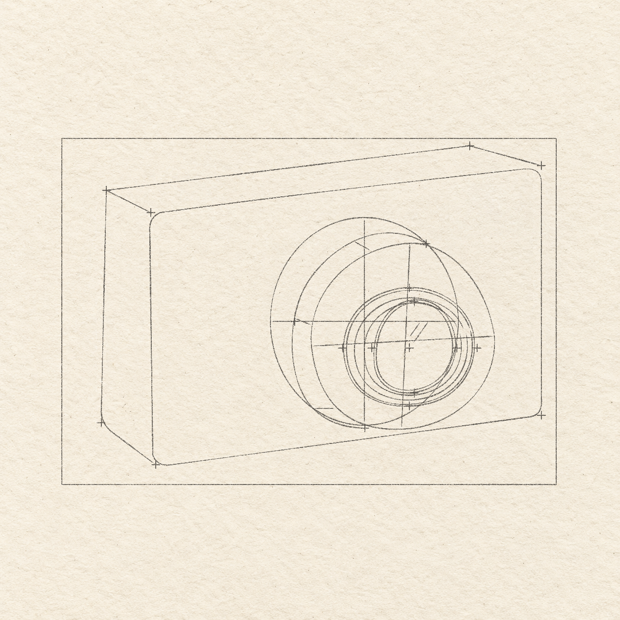
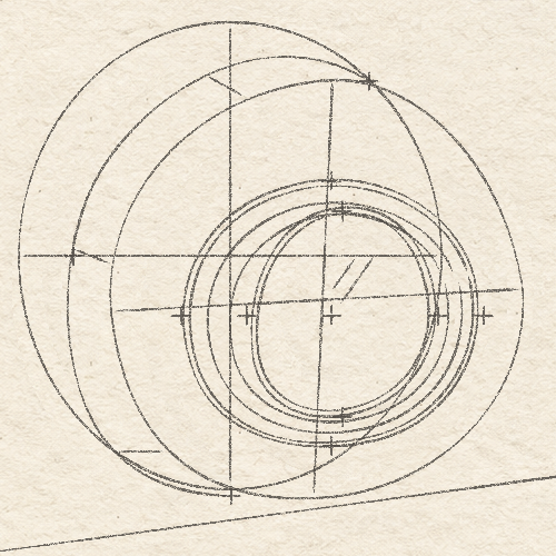
    Three sample rib strokes follow the curved barrel enclosure, while two short parallel reflections stay within the existing central opening.
    Drawing 5A — Rib direction and reflection sketchView larger
    This is the same drawing at a closer scale. Distinguish the intermediate barrel curve, the front-face boundary and the smaller ring/opening; keep their separate paper spaces.
    Detail 5A.1 — Lens boundaries and pale bandsThis is the same drawing at a closer scale. Distinguish the intermediate barrel curve, the front-face boundary and the smaller ring/opening; keep their separate paper spaces.

    Instructions for Drawing 5A — Rib direction and reflection sketch

    1. Inside the barrel strip, sketch three light sample ribs: one near the top, one at the left-middle and one near the bottom. Join the existing enclosing curves with each short stroke. Let their slants change as the barrel turns; do not extend a rib into the front face.
    2. Inside the small opening, draw two short parallel freehand reflection strokes just above its center. Let them rise to the right, one about 4 mm and the other about 6 mm long, with about 1 mm of paper between them. Keep their ends well inside the opening rather than touching its rim. Compare Drawing 5A — Rib direction and reflection sketch.
    Next step — Sketch the five fittings
  6. Step 6 of 11 · Pencil

    Sketch the five fittings

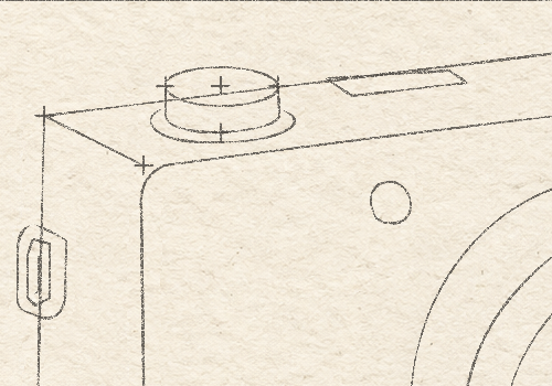
    Four light crosses locate the top dial’s shallow oval width, its center and its lower front edge on the existing top plane.
    Drawing 6A — Top dial placement limitsView larger

    Instructions for Drawing 6A — Top dial placement limits
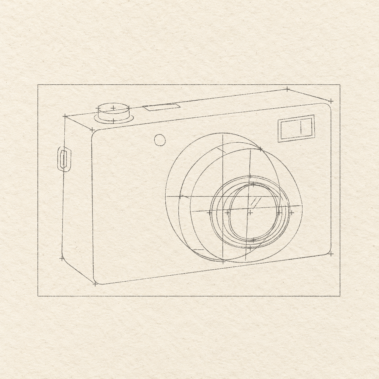
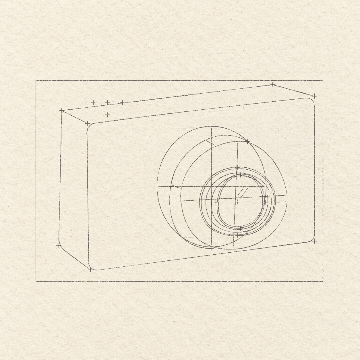
    1. On the top plane, locate the dial center about 2.5 cm across and 8 mm down from the box corner. Mark its left and right limits 5 mm either way, and its lower front edge about 4 mm below the center. Its top will be a shallow oval, not a circle. Compare Drawing 6A — Top dial placement limits.
    The light dial, top slot, viewfinder, front button and left strap loop are all positioned on the existing case, with their internal outlines left pale.
    Drawing 6B — Complete light controls and fittingsView larger
    The shallow top oval and short side are separate. The top stays pale; only the bounded front side receives short hatches when inking.
    Detail 6B.1 — Shallow top dial and its sideThe shallow top oval and short side are separate. The top stays pale; only the bounded front side receives short hatches when inking.
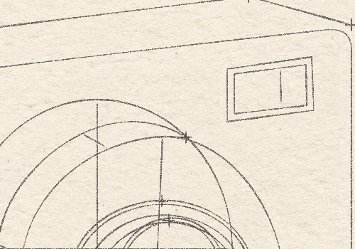
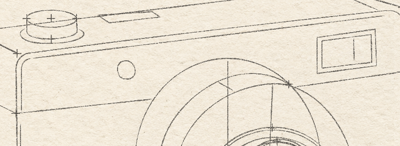
    The light pencil inner frame sits about 1 mm inside the outer edges. The light divider marks the narrow right section. A tiny pencil gap can remain at its end. Leave both sections pale. The divider joins the inner frame in the later ink task.
    Detail 6B.2 — Viewfinder frame and right sectionThe light pencil inner frame sits about 1 mm inside the outer edges. The light divider marks the narrow right section. A tiny pencil gap can remain at its end. Leave both sections pale. The divider joins the inner frame in the later ink task.

    Instructions for Drawing 6B — Complete light controls and fittings

    1. Sketch a shallow freehand oval between the dial’s side limits, about 3 mm high. From its sides, draw two short downward edges and join them with a curved lower edge at the marked depth. Add a slightly wider curved base around it; keep the dial interior pale.
    2. On the top plane, draw a narrow sloping four-sided slot freehand. Keep it about 1.1 cm long and 1 mm deep, starting about 3.5 cm across and 7 mm down from the box corner. Make its long sides follow the existing top-plane slope.
    3. Near the upper-right of the front face, sketch a small tilted rectangular viewfinder freehand, about 1.2 cm wide and 7 mm high. Put its upper-left corner about 8 cm across and 1.2 cm down from the box corner. Follow the front top edge’s slope; draw an inner frame about 1 mm inside the outer edges. Draw the light divider about 3.5 mm left of the inner right edge, following that edge’s slope. Keep it inside the inner frame. A tiny gap at either end is fine in pencil. Leave both spaces pale.
    4. Sketch a small freehand round button about 4 mm wide on the front face, centered about 4.1 cm across and 1.8 cm down from the box corner. Rehearse its curve before drawing and keep its interior pale for now.
    5. On the left case edge, outline a narrow rounded strap loop freehand, about 4 mm wide and 8 mm high. Its top is about 2.1 cm below the box top. Follow the existing left side; add one smaller rounded opening inside the loop, keeping a slim paper gap between its two edges. Add one fine stroke down the opening’s middle, with a short bend left at its lower end. Compare Drawing 6B — Complete light controls and fittings.
    Next step — Plan seams and shadow directions
  7. Step 7 of 11 · Pencil

    Plan seams and shadow directions

    Two small crosses on the existing front side edges locate the case seam below its retained upper corner limits.
    Drawing 7A — Two case seam height marksView larger

    Instructions for Drawing 7A — Two case seam height marks
    1. From the upper-left front corner limit, measure about 1.2 cm down its side edge and mark a cross. On the right side, mark another cross about 1.3 cm below its upper corner limit. These locate the two ends of the exposed front seam before you join them. Compare Drawing 7A — Two case seam height marks.
    Light selected case seams stop at the existing lens and fittings, and two short guide strokes distinguish left-side hatching from the shallower cast-shadow direction.
    Drawing 7B — Case seam and shadow direction sketchView larger
    The pencil seam stops at the current rear oval and front outline. Its final ink stops will follow the later inked lens. The narrow inner border follows the top and left edges with short interruptions.
    Detail 7B.1 — Case seam, inner border and stopping gapsThe pencil seam stops at the current rear oval and front outline. Its final ink stops will follow the later inked lens. The narrow inner border follows the top and left edges with short interruptions.

    Instructions for Drawing 7B — Case seam and shadow direction sketch

    1. Follow the case’s existing slopes. Draw a light seam from the strap’s right edge, halfway down its loop, down-right to the left seam cross. Aim toward the right seam cross, stopping at the rear lens oval. On the right of the lens, restart on the front lens outline and continue gently up-right to the right cross. Recheck both pencil stops after the lens is inked.
    2. Follow the front face’s top edge with a second light line about 1 mm below it, ending about 3 mm before the right side. Round its left end downward into an inner left border, about 1 mm inside the outside edge, and stop at the seam. Restart just below the seam and continue toward the lower-left corner. Leave a roughly 2 mm break about 1 cm above that lower corner, then finish about 3 mm before the bottom edge. Keep a slim paper strip between each border and the outside edge.
    3. On the top plane, start about 1–2 mm inside each back corner and follow the slanting depth edge with a short inset line. Leave about 1 mm of paper before the rounded front corner on the left. On the right, let the inset meet the already drawn front top edge. Do not add another line across the whole top face.
    4. Use the lower BACK-left cross in Drawing 1C — Top and left depth limits. Start the side-plane guide about 1 mm right and 3 mm above that cross; draw a short, straight pencil line 2 mm right and 3 mm up. Start a separate ground guide about 5 mm left and 1 mm above the cross; draw another straight pencil line 5 mm right and about 1 mm up, stopping before the case edge. These are hatching directions, not case edges. Compare Drawing 7B — Case seam and shadow direction sketch.
    Next step — Ink the supported lens
  8. Step 8 of 11 · Fineliner

    Ink the supported lens

    The complete dark fineliner lens sits over the retained light construction: continuous barrel curves, front rings, a narrow dark opening rim, ribbing and two reflections.
    Drawing 8A — Complete fineliner lensView larger
    This is the same drawing at a closer scale. Distinguish the intermediate barrel curve, the front-face boundary and the smaller ring/opening; keep their separate paper spaces.
    Detail 8A.1 — Lens boundaries and pale bandsThis is the same drawing at a closer scale. Distinguish the intermediate barrel curve, the front-face boundary and the smaller ring/opening; keep their separate paper spaces.

    Instructions for Drawing 8A — Complete fineliner lens

    1. With a fine black fineliner, follow the prepared lens routes. Draw the exposed rear and intermediate barrel curves, then the complete front-face outline; omit rear curve sections hidden behind the front face. Keep the broad front face as paper. Keep the temporary pencil curves and seam tips light until final erasing.
    2. Follow the prepared inner ring and opening curves in ink. Build the narrow dark rim around the opening with short curved strokes between its existing close boundaries. Preserve the central opening and the pale strip between the dark rim and larger ring; do not fill the whole front face.
    3. Add short fineliner ribs across the prepared barrel strip, following the changing slants of the three sample strokes. Keep their ends on the two existing curved boundaries and leave narrow paper gaps between them. Choose the spacing by eye, then ink the two already sketched reflections inside the opening. Compare Drawing 8A — Complete fineliner lens.
    Next step — Ink the supported fittings
  9. Step 9 of 11 · Fineliner

    Ink the supported fittings

    The dial, top slot, viewfinder and button are inked with their restrained internal bands or hatches. The complete strap and case remain in light pencil for the next task.
    Drawing 9A — Ink four prepared controlsView larger
    The dial has an inked shallow top oval, short sides and a curved base. Short upright hatches now fill only the bounded front side; the top oval remains pale paper.
    Detail 9A.1 — Shallow top dial and its sideThe dial has an inked shallow top oval, short sides and a curved base. Short upright hatches now fill only the bounded front side; the top oval remains pale paper.
    The inner frame sits about 1 mm inside the outside edges. The divider bounds a narrow right section; preserve paper slits between the remaining diagonal hatches.
    Detail 9A.2 — Viewfinder frame and right sectionThe inner frame sits about 1 mm inside the outside edges. The divider bounds a narrow right section; preserve paper slits between the remaining diagonal hatches.

    Instructions for Drawing 9A — Ink four prepared controls

    1. Follow the dial’s complete light top, side and base outlines with ink. Then add a small group of short upright hatches on its front side, stopping at the existing top and bottom curves. Leave its shallow top oval as paper.
    2. Ink the two viewfinder frames. Follow the pencil divider and bring its ends to the inner top and bottom edges. Darken the slim surrounding frame and the narrow right section, then add a few upward-right diagonal hatches inside the remaining opening. Keep clear paper slits between those hatches; do not turn the whole window solid black.
    3. Follow the small round button outline in ink, then add a few short upward-right hatch strokes inside it. Keep the strokes clipped to the existing button edge and leave tiny pale gaps. The neighboring case face stays open.
    4. Follow the top slot’s four light edges with the fineliner and leave its interior pale. Keep the strap loop in pencil for now; it will be inked together with the case in the next task. Compare Drawing 9A — Ink four prepared controls.
    Next step — Ink the case, then its local shadows
  10. Step 10 of 11 · Fineliner

    Ink the case, then its local shadows

    The complete camera case is inked around its existing lens and fittings. Fine diagonal side-plane hatching and separate shallow ground strokes follow the completed contours; light construction remains for cleanup.
    Drawing 10A — Ink case contours, then its shadowsView larger

    Instructions for Drawing 10A — Ink case contours, then its shadows

    1. First follow the prepared strap loop’s outside edge and smaller inner opening with the fineliner. Ink the fine stroke down the strap opening’s middle and its short left bend at the bottom. Preserve the narrow paper gap and leave the opening pale.
    2. Follow the complete light case routes in fineliner, smoothing the straight spans and rounding the already planned corners. Stop at the existing inked dial, strap and lens where they overlap the case; do not draw hidden edges through them. Keep the top and front faces pale.
    3. Follow the left seam’s pencil direction with ink until it meets your already inked rear lens edge. Extend it only if the pencil stops short, by up to about 2 mm; keep the seam out of the lens. On the right, start at your inked front lens edge and continue to the existing right seam cross. Leave any unused pencil tip for final erasing.
    4. Follow the prepared top and left inner borders and the two top-plane depth insets with ink. Keep their planned pale strips, short gaps and finite ends. Preserve a slim paper strip between each border and the outside case edge.
    5. After the case contour exists, add a small group of short diagonal fineliner hatches inside the lower-left side plane. Follow the steeper sample direction, start beside the existing outside edge and stop before the front face. Let stroke lengths vary and leave narrow paper gaps; keep these strokes off the broad front face.
    6. Add a separate small group of shallow ground strokes just left of the rounded BACK-left bend, beside the ground guide placed from the lower back-left cross. Follow that guide’s slope and keep the strokes outside the case, within about 8 mm of it. Make the outer strokes shorter. Add only a few tiny contact strokes just below the lens; choose their spacing by eye and leave the rest of the page blank. Compare Drawing 10A — Ink case contours, then its shadows.
    Next step — Erase the dry-tested pencil guides
  11. Step 11 of 11 · Cleanup

    Erase the dry-tested pencil guides

    The finished fineliner camera has a rounded three-quarter case, complete ribbed lens, five fittings and limited side/ground hatching. All temporary pencil guides have been removed.
    Drawing 11A — Finished fineliner cameraView larger

    Instructions for Drawing 11A — Finished fineliner camera

    1. On a scrap of the same paper, fill a small patch with the same fineliner. Rub the patch gently with your eraser. If it smears, wait and test again. Once it stops smearing, lift the working box, placement crosses, lens crosses and envelopes, rehearsal contours and direction samples in short sections. Preserve the finished black ink and all pale gaps; do not add extra hatching to hide a missed pencil mark. Compare Drawing 11A — Finished fineliner camera.
    Back to the tutorial

If something looks off

The lens looks like one flat circle

Keep the rear and front placements separate. The front face sits farther right and down, and the visible curved barrel enclosure between them gives it depth.

A case seam crosses the lens

In pencil, stop at the named rear oval and front outline. After inking the lens, use its actual inked edges for the final seam stops. Leave the small unused pencil tip until cleanup; do not ink through the lens.

The lens opening becomes a black disk

Fill only the planned narrow rim with curved strokes. Preserve the central paper opening and the pale strips between the neighboring rings.

The side and ground shadows blend together

Use the steeper sample inside the left side plane. The separate shallow ground guide is just left and above the lower BACK-left cross, outside the case. Keep each hatch group beside its own guide and within the limits given in Drawing 10A — Ink case contours, then its shadows.